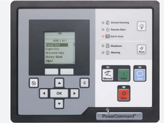
This instruction show you guide on how to solve PCC2300 PowerCommand HMI unable to communicate with PCC.
Related Contents:
2025 InPower V16 Pro V12 Diagnostic Software Free Download
PowerCommand Diagnostic 9 Pin Adapter Cable for InPower
Logic:
HMI cannot establish communication with the PCC.
Possible Causes:
1.J29 is not plugged in properly to the HMI.
2.Defective PCCNet interface at J25 of the PCC.
3.Another faulty device is present in the PCCNet network.
Diagnosis and Repair:
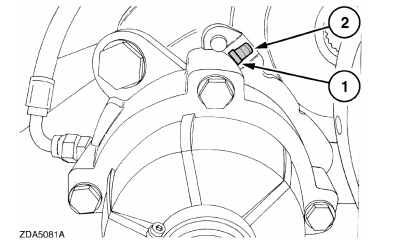
1 Inspect if the connector J29 is properly connected to the HMI. J29 connects the HMI to the PCC. Check the J29–J25 harness.
2 Defective PCCNet interface at J25 of the PCC. Troubleshoot the PCC by connecting it to InPower through TB15. Once connected, go to Setup -> PCCNet setup in Inpower. If the value of “Active
PCCNet HMI220 (or HMI320) Operator Panels” is equal to the number of operator panels connected, the HMI is successfully communicating with the PCC.
a If you see the correct number of other PCCNet devices (ex. AUX101, annunciator, etc.) but not of operator panels, then the HMI is faulty and should be replaced.
b If the status of none of the PCCNet device is dispalyed correctly, then the PCC is not able tocommunicate the PCCNet signal. Troubleshoot the PCC and replace it if necessary.
3 Another PCCNet device is faulty in the network. Isolate each device and test for communication to find the root cause.