Here is the instruction show you guide on how to oxidation catalyst air clean for Detroit GHG17 engine.
Before performing this service routine, the cause of the DOC plugging should be found and corrected. Typical DOC plugging causes are vehicle duty cycles that are: stop-and-go, have excessive idle time, have stationary PTO operation, or have a hardware issue with the engine or vehicle. Perform the “ATD Checklist” to review these possible causes and correct them before running this service routine.
The Diesel Oxidation Catalyst (DOC) air cleaning will remove soot that has built up on the face of the DOC. Air cleaning the DOC will reduce the aftertreatment inlet pressure, allowing for a parked regeneration to safely run without damaging the engine.
Related Contents
DDDL 8.20 2024
Nexiq USB Link 3 Adapter
DOC air cleaning kit DSN0ATZ16002 is compatible for use on EPA10 1-Box, GHG14 1-Box, GHG17 1-Box, Gen 5 1-Box (with dual DOC) and 2016-2021 MDEG 1-Box aftertreatment systems. You will also need an air gun with a six-inch tip and shop vacuum equipped with a dust bag to capture soot removed from the aftertreatment. A shop vacuum with a 2 ½ inch diameter hose will provide the best sealing around the inlet reduction cone.
Check as follows:
WARNING
PERSONAL INJURY
Use caution when handling and cleaning the Diesel Oxidation Catalyst (DOC). Personal protective equipment and clothing in accordance with all applicable federal, state and local laws or regulations should be used. Contents of the ash and soot removed from the DOC may be classified as a hazardous waste under federal, state and/or local laws or regulations. Hazardous wastes must be handled and disposed of in accordance with all applicable federal, state and local laws or regulations.
1 Remove the 1-BOX™ aftertreatment from the vehicle. Refer to section “Removal of the 1-BOX™ from the Vehicle” .
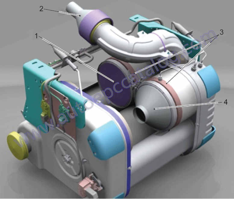
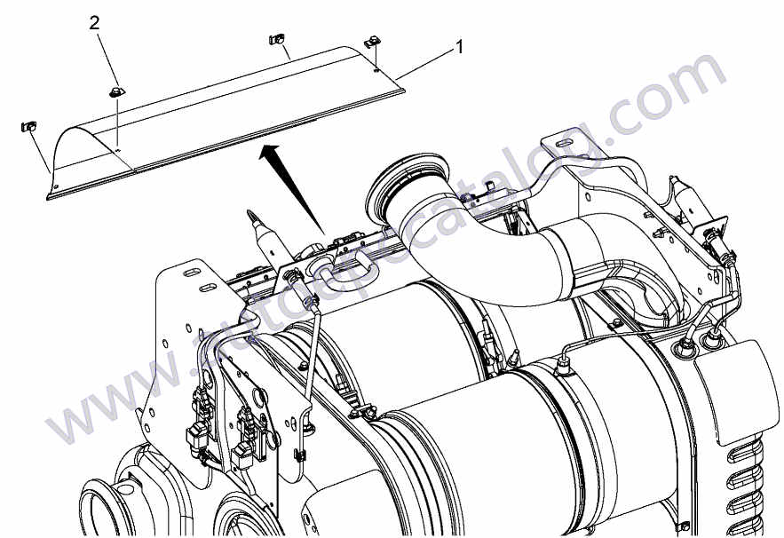
2 Remove the outboard heat shield (1) from the 1-BOX™ configuration by disengaging the folded flange on the top of the outboard heat shield.
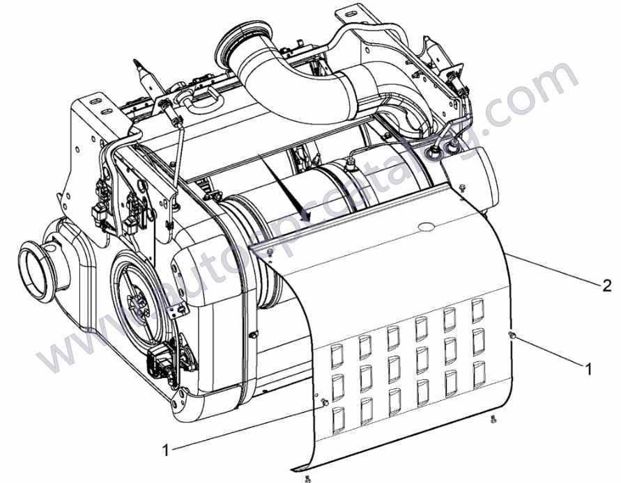
3 Remove the four mounting bolts (2) from the inboard heat shield (1). Slide the inboard heat shield down allowing better access to the inboard Diesel Particulate Filter (DPF), V-band and flat band clamp.
Note : Record the orientation of the bands and clamps. These components need to be installed in the same location.
4 Loosen the outboard V-band and flat band clamps on the outboard DPF.
5 Slide the outboard flat band clamp inward and the V-band clamp outward on the outboard DPF.
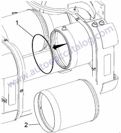
6 Remove the outboard DPF assembly (2) from the 1-BOX™ configuration and discard the flat band gasket (1).
7 Loosen the V-band and flat band clamps on the inboard DPF.
8 Slide the inboard flat band clamp inward and the V-band clamp outward on the inboard DPF.
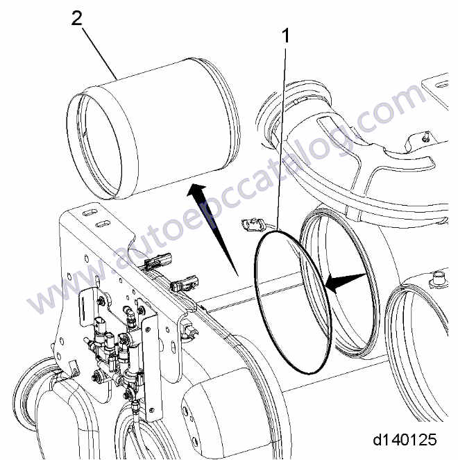
Remove the inboard DPF (2) from the 1-BOX™ configuration and discard the flat band gasket (1).
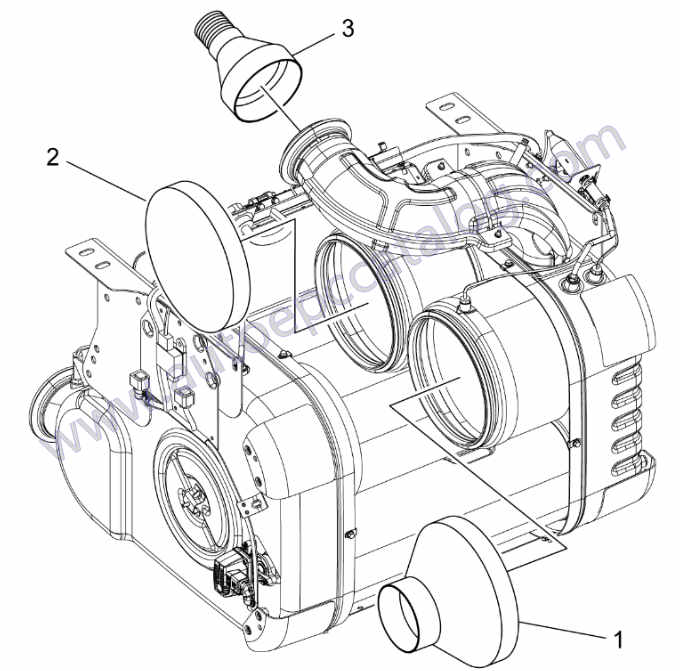
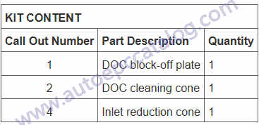
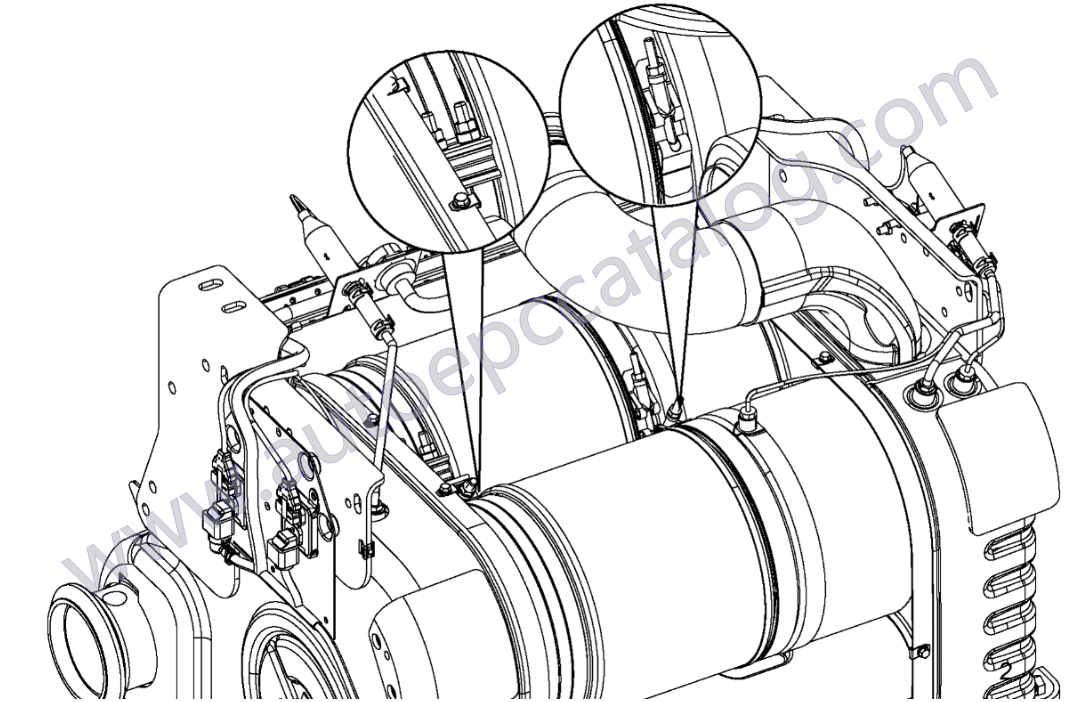
10 Using DOC face cleaning kit W470589239100, slide the inlet reduction cone (3) over the aftertreatment inlet. See graphic below.
11 Install the DOC block-off plate (2) over the inboard DOC and hand-tighten clamp.
12 Attach the DOC cleaning cone (1) to the outboard DOC and hand-tighten clamp.
13 Attach the shop vacuum hose to the aftertreatment reduction cone (3).
CAUTION
EYE INJURY
To avoid injury from flying debris, wear a face shield or goggles.
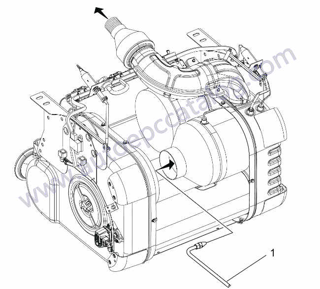
14 Turn on the shop vacuum; you should be able to feel suction if you place your hand momentarily over the DOC cleaning cone opening.
NOTICE
Regulate air pressure to a maximum of 120 psi to prevent damage to the substrate.
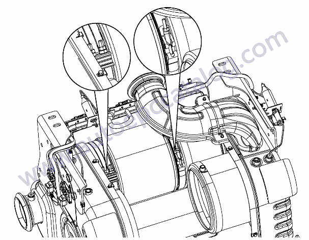
15 Place the air gun nozzle inside the cleaning cone and keep the air gun tip 25 mm (1 in.) away from the DOC to prevent damage to the brick.
16 Start blowing compressed air into the DOC cleaning cone. Move the air nozzle in a circular pattern, starting from the outer edge and work your way inward to center of the DOC. Continue this motion for several minutes.
17 Remove the DOC cleaning cone.
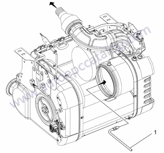
18 Continue blowing air into the DOC using a slow sweeping motion, making sure to cover 100% of the DOC surface. Keep the air gun tip 25mm (1 in.) away from the DOC to prevent damage to the brick.
19 Move the block-off plate to the outboard DOC and install the cleaning cone onto the inboard DOC.
20 Place the air gun nozzle inside the cleaning cone, keep the air gun tip 25 mm (1 in.) away from the DOC to prevent damage to the brick. Start blowing compressed air into the DOC cleaning cone. Move the air nozzle in a circular pattern, starting from the outer edge and work your way inward to the center of the DOC. Continue this motion for several minutes.
21 Remove the inboard DOC cleaning cone.
22 Continue blowing air into the inboard DOC using a slow sweeping motion making sure to cover 100% of the DOC surface. Keep the air gun tip 25 mm (1 in.) away from the DOC to prevent damage to the brick.
23 Disconnect the vacuum and remove the inlet reduction cone and DOC block-off plate.
24 After each DOC has been air cleaned, reinstall both Diesel Particulate Filters (DPF) using new flat band clamps and V-band gaskets.
25 Reinstall the aftertreatment.
26 Run a Parked Regen to verify DOC inlet pressure and check for proper NOx conversion.