Posted on

How to Solve Serdia 4.0 Software of Dataset is Not Known

How to Solve Serdia 4.0 Software of Dataset is Not Known

Deutz Serdia 4.0 “The software of the dataset, which you want to flash, is not known in this SerDia 4.0 version.It is therefore not possible to flash this dataset. Make sure that SerDia4.0 is up to date.”

How to Solve Serdia 4.0 Software of Dataset is Not Known

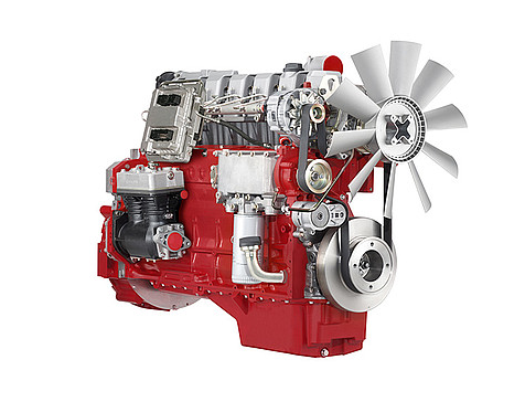
Some customers get above “software of the dataset is not known” error when they perform Deutz engine ECU flash.Here autoepccatalog.com share the solution to solve it.


Software of the dataset error is due to old version Serdia 4.0 software you used v16.00.00

The solution is you need to update your Serdia 4.0 v16.00.00 to v18.02.00,but currently v16.00.00 can not be update to v18.02.00.If you do update that will cause your Serdia 4.0 can not work anymore.


So solution is you need to buy new version Deutz Serdia 4.0 v18.02.00

Posted on

MANITOU MT6034 Construction Telehandlers Lubrication Lockout Tests Guide

MANITOU MTA 6034

Here is the instruction show you guide on how to perform lubrication lockout test for MANITOU MT6034 construction telehandlers.

MANITOU MTA 6034

Related Contents:

2026 Manitou I.V Interactive View Diagnostic Software


Procedures:

To test the transmission and joystick control lockout logic:

1. Shift transmission into “F” (Forward) and increase the engine speed slightly.

The transmission should remain de-clutched,allowing the engine to increase speed easily.

Return the transmission selector to “N” (Neutral) after the check.


2. Have an assistant move the remote shutdown switch to “Dis-engaged.”

The joystick control should now be disabled, so that boom raise/lower and extend/retract will no longer function.

Have the assistant move the remote shutdown switch to “Engaged” after the check.


3. Tilt the frame to the right slightly more than two degrees.

The joystick control should now be disabled so that boom raise/lower and extend/retract no longer function.


Repeat the procedure with the frame tilted to the left.

Return the frame to a level position after the checks.

Posted on

Liebherr R9600 Excavator Water Separator Drain

Liebherr R9600 Excavator Water Separator Drain

This instruction show you guide on how to drain the water separator fuel system for Liebherr R9600 excavator.

Liebherr R9600 Excavator Water Separator Drain

Related Contents:

2026 LIEBHERR LiDIA Diagnostic Software

LIEBHERR Diagnostic Kit


Make sure that the following preconditions are met:

The machine is safely parked on firm and level ground.

The Diesel engine is stopped.

Make sure that the following tools are available:

Used fuel container

Put the used fuel container below the water separator.

Open the drain valve 1 manually: turn the drain valve 1 counterclockwise until it moves down.

Water flows out of the drain valve 1.

Drain the water into the used fuel container until clean fuel flows out.


NOTICE

Incorrect tightening of the drain valve!

Risk of damage to the threads of the drain valve.

Tighten the drain valve manually.

Do not tighten the drain valve too much.

When clean fuel flows out, close the drain valve 1 manually: lift it and turn it clockwise to tighten it.

Refer also to the manual of the Diesel engine manufacturer.

Posted on

FENDT 900 COM III Series Starter Control System Diagram

FENDT 900 COM III Series Starter Control System Diagram (1)

On the FENDT 900 COM III series, as on all other COM III tractors, the starter is controlled by means of the A051 – ECU,engine control unit (EDC 7)..

FENDT 900 COM III Series Starter Control System Diagram (1)

When all input signals are present, the K065 – Starter relay is energised by the A051 – ECU, engine control unit (EDC 7)..


What your need?

AGCO 2×4 CANUSB Diagnostic Tool

Fendt Fendias 2024v2

AGCO Fendt NA Parts Books & Workshop Service Manuals

2026 AGCO EDT Diagnostic Software


Start signals include:

– Supply voltage at terminals 30, 15, 31

S012 – Switch, starter lockout +UB at pin 66


S002 – Switch, ignition terminal 50a +UB at pin 74

During the start process, the A051 – ECU, engine control unit (EDC 7). also requires the following signals:

– Start quantities released by the immobiliser control unit via the G bus

– A speed signal from the B085 – Camshaft speed sensor or the B088 – Crankshaft speed sensor

NOTE: If the A051 – ECU, engine control unit (EDC 7). does not detect a speed signal after about 5 seconds, the start process is aborted.


The start process is aborted for the following reasons:

– Without a speed signal, the A051 – ECU, engine control unit (EDC 7). cannot classify the rotational speed of the engine, speed control

– Without a speed signal, the A051 – ECU, engine control unit (EDC 7). cannot assign the injection time


B085 – Camshaft speed sensor TDC cylinder 1 ignition, or

B088 – Crankshaft speed sensor TDC cylinder 1/6

FENDT 900 COM III Series Starter Control System Diagram (2)

Posted on

How to Solve Deutz 83/975/FanCD FAN Actuator Error

This instruction show you guide on how to solve Deutz trouble code 83/975/FanCD FAN actuator error.

Fan power stage: the current drain measured by ECU is out of the target range or the maximum permissible temperature of the  ECU component for power supply of the actuator is exceeded

Deutz EMR3 engine control unit ArHt1.

Related Contents:

Deutz Serdia 4.0

Deutz DECOM


Error codes

DEUTZ-Errorcode: 83

BlinkCode (short-long-short): 2 – 3 – 8

SPN: 975


possible FMI:

3: Voltage to high or short circuit to +Ubatt

4: Voltage to low or short circuit to -Ubatt

5: current to low or broken wire

2: data stream is defective


Error detection

Errorlamp shows permanent light. Entry in errormemory.


Possible reason for error

cable break or short circuit, sensor defective, connection cable damaged


Take actions for error repair

Check cabling, sensor defect, check sensor and if necessary  replace it, check connection cable and if necessary repair or replace it other error properties


System reaction: Warning, shutoff output

Behaviour error lamp: permanent light


Selfhealing: no

Signal Priority: 2

Posted on

Kubota L3301 L3901 Tractor Relief Valve Setting Pressure

Kubota L3301 L3901 Tractor Relief Valve Setting Pressure (1)

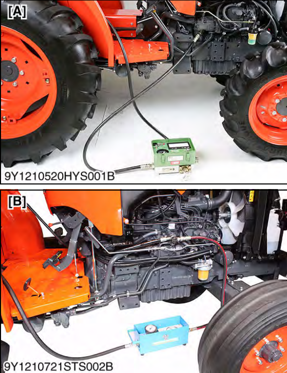
Here is the instruction show you guide on how to perform relief valve setting pressure for Kubota L3301 L3901.


Related Contents:

[06.2025] Kubota DiagMaster 25.02.01 Level 9 Takechi,Manitou,Carrier,Nonself

[06.2021]Kubota EPC PAD KDG+LinkOne EPC 2003 2 in 1 VMware

Genuine Kubota DST-i Diagnostic Adapter


Relief Valve Setting Pressure

1 Disconnect the power steering delivery pipe joint bolt.

2 Install the adaptor E instead of joint bolt, and then set a thread joint, cable and pressure gauge.

3 Start the engine and set the engine speed at max. speed.

Kubota L3301 L3901 Tractor Relief Valve Setting Pressure (1)

4 Fully turn the steering wheel to the left or right and read the pressure when the relief valve functions.

5 Stop the engine.

6 If the pressure is not within the factory specifications, check the pump delivery line, and adjust relief valve setting pressure by turning adjusting screw (1).

Kubota L3301 L3901 Tractor Relief Valve Setting Pressure (2)

Posted on

How to Use JPRO Software to Perform Output Component Test for Bendix?

How to Use JPRO Software to Perform Output Component Test for Bendix

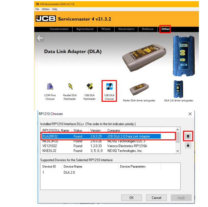
Here is the guide on how to use JPRO diagnostic software to do output component test for Bendix AutoVue 3G LDW system and Bendix SafeDirect Web Portal Processor (3G and 5G).


Related Contents:

JPRO Noregon Diagnostics 2025

Noregon JPRO DLA+ 2.0 Adapter


This test checks for proper functionality of connected alert systems, including: Speaker Feedback, Haptic Feedback, and Stereo Mute.

1 Select the Output Component Test and press Enter or the Start button.

2 The test dialog will be displayed.

How to Use JPRO Software to Perform Output Component Test for Bendix


3 Ensure the stereo is muted, then click the desired left or right test button. The selected speaker or haptic motor will be activated until the selected button is clicked again to stop the test.

4 To perform the Stereo Mute test, ensure the stereo is turned on before clicking the button to begin the test.

Select the button again to stop the test.

5 When done, press the Exit button to return to the test selection dialog

Posted on

AGCO Machine Error Boost Pressure Above Normal SPN 102 FMI 16 Solution

AGCO Machine

Here is the instruction show you guide on how to solve AGCO machine error code SPN 102 FMI 16 boost pressure above normal solution.

AGCO Machine


Related Contents:

AGCO 2×4 CANUSB Interface Diagnostics

2026 AGCO EDT Electronic Diagnostic Tool


Description

The measured boost pressure rises above the warning limit during operation.


Failure Mode Indicator

FMI 16 – Above normal operating range – moderately severe.


Failure Mode

Fault code is stored and warning lamp is activated. Engine speed is limited to 1500 rpm (SL2) and engine power will be reduced (FL1). CAN message indicates active fault. No recovery before system reset.


Possible Cause

  • Too high fuel injection quantity (mg/str) for the engine type (tuning chip)
  • Incorrect nozzles for the engine type
  • Incorrect turbo charger for the engine type
  • Boost pressure wiring is defective
  • Boost pressure sensor is defective
  • Control unit is defective


Diagnosis and Solution

Find cause for the high boost pressure indication:

  • Check, that the control system is configured according to the original specification and no additional devices have been attached.
  • Check that the nozzles and the turbocharger meet the original specifications.
  • Check the boost pressure sensor wiring, connectors and contact surfaces of the connector pins (possible oxidation).


Boost Pressure Intake Manifold Temperature Sensor

  • Check the boost pressure sensor operation.


Boost Pressure Intake Manifold Temperature Sensor

  • Check the ECU operation with another EEM3 controller. If the system is functional and the fault is not active with the replacement ECU, then the original ECU is defective.

ECU Replacement

Posted on

How to Solve Scania Truck ALM 310 Siren,Short Circuit

How to solve Scania truck ALM 310 siren,short circuit does not work correctly.


Preparations:

Scania SDP3 2.69.3 Truck Diagnostic Software

Scania Multi EPC 2026

Scania VCI3 High quality


Error identification

Siren N9 is short-circuited to ground.


Cause

Fault in harness-to-component connectors or cable harness for siren N9.

Fault in siren N9.

Faulty ALM control unit E7.


Symptom

The siren does not work correctly.


Action

1 Disconnect siren N9.

2 Measure against ground and voltage on the pins in the nearest harness-to-component connector leading to control unit pin A11.

3 Disconnect the harness-to-component connector on the control unit.

4 Measure for short circuits throughout the cable harness.

5 If there are several harness-to-component connectors between the component and the control unit, also measure these to locate the fault.

6 If the fault is not in the cable harness or the component, it is probably an internal fault in the control unit.


Posted on

Caterpillar C9 Engine PTO Throttle Signal Invalid 29 30-8 Trouble Repair Solution

Caterpillar C9 Engine

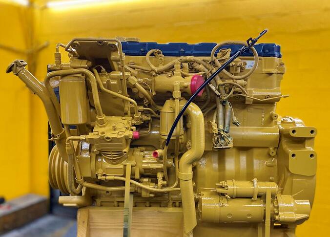
This instruction show you guide on how to solve Caterpillar C9 Engine trouble code 29 30-8 PTO throttle signal invalid error.

Caterpillar C9 Engine

Related Contents:

CAT ET 2025A

CAT Comm 3 478-0235

Caterpillar 18 digits factory password calculator


The Engine Control Module (ECM) detects the following conditions:


The “PTO Configuration” is programmed to “Remote Throttle”.

The ECM is not receiving a valid signal from the PTO throttle.

The ECM has been powered for at least three seconds.


A remote accelerator position sensor may be used for PTO purposes The remote accelerator position sensor should be connected to terminal 1Pr-68 of the Engine Control Module ECM).Before the ECM will respond to the remote accelerator position sensor, the ECM”PTO Configuration” must be programmed to “Remote Throttle”, and the “PTO On/Off Switch” must be in the ON position.


The remote accelerator position sensor must be powered from the vehicle battery(+ 12 V).A +12 V version of the accelerator position sensor must be used for the remote accelerator position sensor,and the +8 V version for the accelerator pedal position sensor must be used in the cab.


The ECM will not respond to the remote accelerator position sensor while 253-02 diagnostic-code is active.Refer to Troubleshooting,”ECM Memoy-Test if 253-02 diagnostic code is active.


The remote accelerator position sensor provides a throttle position signal to the ECM.The output of the remote accelerator position sensor is a constant frequency signal with a pulse width that varies with the position of the sensor.This output signal is referred to as either a duty cycle or a pulse width modulated signal (PWM).


The output signal of the remote accelerator position sensor is expressed as a percentage between 3 and 100 percent.The accelerator position sensor will produce a duty cycle of 10 to 22 percent at low idle and 75 to 90 percent when the sensor is fully actuated. The percent of duty cycle is translated in the ECM into a throttle position of 3 to 100 percent.


If the vehicle is using the ECM dedicated PTO functions, the accelerator position sensor will be ignored while the engine is in “PTO Mode’ and the “PTO Configuration” is programmed to the “Remote Throttle” option.


The ECM is in”PTO Mode” while the PTO on/off switch is on. This can be checked through the status screen on Caterpillar Electronic Technician (ET).


The ECM will not respond to the remote accelerator position sensor when both of the following conditions are met:


The PTO on/off circuit is switched from the OFF position to the ON position.


The ECM reads the remote accelerator position sensor above low idle.


This prevents the engine from experiencing unexpected acceleration or sudden acceleration when the PTO on/off circuit is turned on.The remote accelerator position sensor must return to low idle before the ECM will respond. The ECM must also see a transition from the OFF position to the ON position in the PIO on/off switch in order to Allow the other PIO speed control functions to operate.If the engine is started with the PTO on/off switch in the ON position, the accelerator will respond. The response will occur only if the accelerator pedal is first returned to the low idle position, The other engine speed controls will not respond.


Probable Causes:

1 ECM Connection

2 Remote accelerator position sensor

3 Remote accelerator position sensor harness

4 Remote accelerator throttle