Posted on

Caterpillar C9 Engine PTO Engine Shutdown Switch Voltage Low

Caterpillar C9 engine PID 186-4 PTO engine shutdown switch voltage low solution.

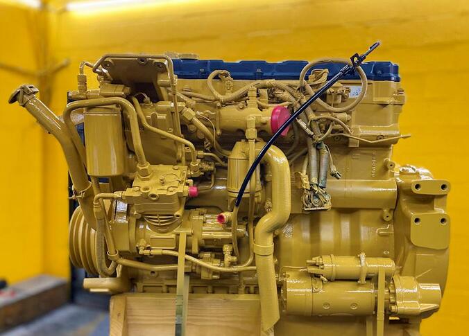
Caterpillar C9 Engine

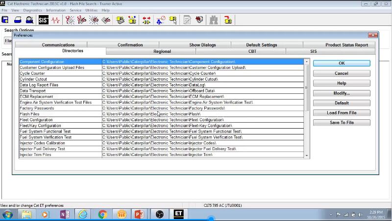
Caterpillar CAT ET 2023C

CAT Comm Adapter 3


A short to ground exists in the wiring for the PTO engine shutdown switch. The parameter “PTO Engine Shutdown Switch” must be programmed to “J1/P1:7” or “J1/P1:23”.


If the vehicle speed is not equal to zero, or if there are active vehicle speed faults, the engine will go to low idle. The engine will not shut down when the vehicle speed falls to zero. When the PTO engine shutdown switch is pressed, a 186-14 will become active. The code will stay active until the engine shuts down. When the engine shuts down, the code will be loggged.


Possible Causes:

1) ECM Connection/Harness

2) PTO Shutdown Switch Failure

3) ECM Failure

4) Wiring between PTO shutdown switch and ECM

Posted on

How to Use CAT ET Service Tool Auto Retarder Test Function

Caterpillar ET Service Tool diagnostic software Auto Retarder Test function allows the operation of the Auto Retarder Control (ARC) system to be verified while the machine is stationary. The ARC outputs are activated and monitored for correct operation.


Related Contents:

Caterpillar CAT ET 2023C 2022A Service Tool

Caterpillar 18 Digits Factory Password

Cat Com 3 adapter 478-0235

CAT SIS 2021 EPC+Service Manual


Accessing

To run the Auto Retarder Test function, select “Diagnostic Tests” from the Diagnostics menu, and then select “Auto Retarder Test” from the submenu. The Auto Retarder Test will be displayed.


Screen Layout

The Auto Retarder Test screen has the following areas:


Display Area

The Auto Retarder Test display area has three columns:

Description – Provides the name of the parameter set to run the test

Required Condition – Displays the value that the parameter must meet in order to run the test.

Actual Value – Displays the actual value of the required condition parameters.


Status Parameter Area

The Auto Retarder Test status parameter area lists parameters and their current values. The ARC Control Solenoid displays the position in percentage of the ARC Control Solenoid. The ARC Pressure Switch Status displays if the status is “High” or “Low.”


Status Line

The Auto Retarder Test status line displays if the test is “On” or “Off.”


Buttons

The buttons available in the Auto Retarder screen are:

Start – Click to start the test. When clicked, “On” will be displayed in the status line, and the button will be disabled until the test is stopped.

Stop – Click to stop the test. When clicked, “Off” will be displayed in the status line, and the button will be disabled until Start is clicked again.

Posted on

How to Use CAT ET 2023A Diagnostic Software APN Programming Function?

Caterpillar ET Diagnostic Software Beginner Video Guide (5)

Caterpillar ET 2023A APN Programming function provides the capability to program Access Point Name information in Product Link in order for cellular network communication to occur.


CAT ET 2023A Diagnostic Software

CAT Comm Adapter 3


Accessing

To run the APN Programming function, select “APN Programming” from the Service menu. The APN Programming screen is displayed.


Screen Layout

The APN Programming screen has the following areas:


APN Configuration Area

The Current Access Point Information display area includes the following information:


APN Configuration Status

SIM Card Status

Region*

Carrier*

Access Point Name*

User Name

SIM PIN Code

* – indicates a pull-down menu


Buttons

The button available in the APN Programming screen :

Change – Click this button to change the currently programmed Access Point Information.

Check Status – Click this button for APN Configuration status updates

Import – Click this button to import APN information from a file

Posted on

How to Install WinPcap for CAT ET 2023A Diagnostic Software

How to Install WinPcap for CAT ET 2023A Diagnostic Software (1)

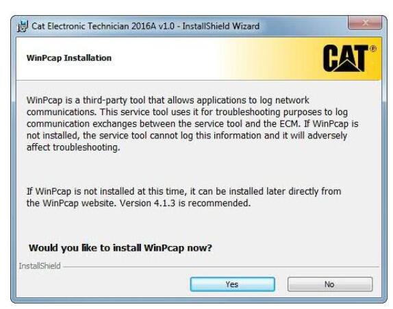
WinPcap is the third-part tool that allows application to log network communications.This service tool uses it for troubleshooting purposes to log communication exchanges between the service tool and the ECM.If WinPcap is not installed,the service tool can not log this information and it will adversely affect troubleshooting.


If WinPcap is not installed at this time,it can be installed later directly from the WinPcap website.

During the installation of Cat ET, the user will be prompted to install WinPcap. Follow the prompts for the installation.

Note:This will only occur if Cat ET or an earlier version of WinPcap has not been installed.


Preparation:
CAT ET 2023A Diagnostic Software

Caterpillar Diagnostic Adapter 3


How to Install WinPcap?

Step 1: Click “Yes.”


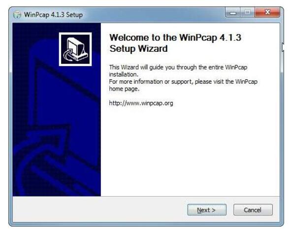
Step 2: Click “Next>” to allow the wizard to guide you through the installation.


Step 3: Read the WinPcap end users license agreement and click the “I Agree” button.


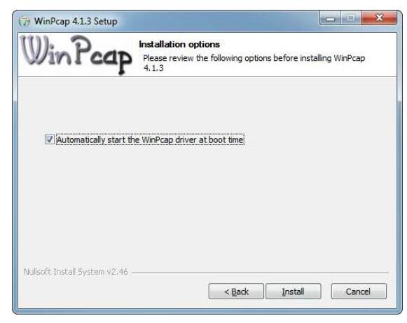
Step 4: Verify that the box allowing the WinPcap driver to automatically start at the boot time is checked.
Then click the “Install” button at the bottom of the dialog box.

How to Install WinPcap for CAT ET 2023A Diagnostic Software (4)


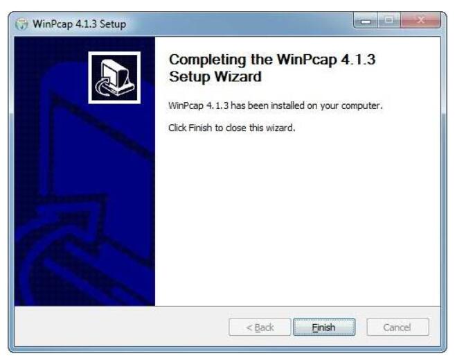
Step 5: Click the “Finish” button to finish the wizard setup of WinPcap.

How to Install WinPcap for CAT ET 2023A Diagnostic Software (5)

Posted on

How to Use CAT ET Diagnostic Software ECM Configuration Function?

CAT ET 2023A (4)

The Configuration function allows configurable information on all available ECMs to be viewed and changed.

CAT ET 2023A (4)

Preparations:

CAT ET 2023A

CAT Communication Adapter 3


Accessing

The Configuration function may be accessed up to three ways:

  1. Select “Configuration” from the Service menu.
  1. Press F5 if the default function keys are set
  1. Click the Configuration Tool icon if the default is set.

Screen Layout

The Configuration screen has the following areas:

Tree Area

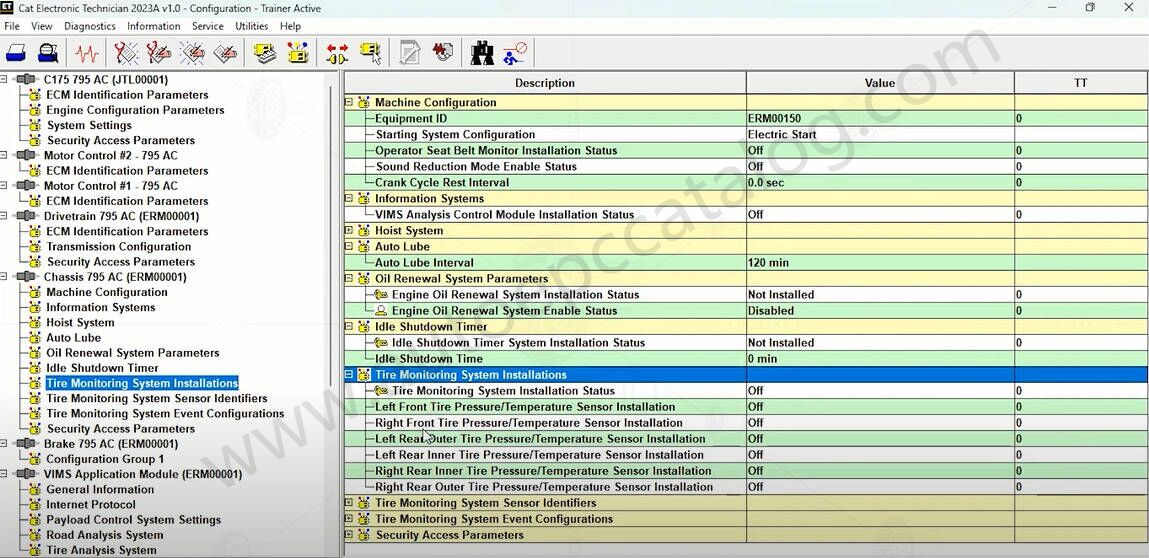
The tree area is located on the left side of the screen. The names of each ECM on the data link are listed under the Available ECM(s) folder. Configuration Groups are listed under each ECM.

To view an individual group of parameters, click on one of the Configuration Groups. The selected Configuration Groups parameters will appear in the display area.

Display Area

The display area is located on the right side of the screen. To view a group of parameters, click on the plus [+] symbol to the left of a selected Configuration Group. The corresponding configuration parameters will be expanded.

Note: Information in both the Tree Area and Display area can be accessed using the arrow keys on the keyboard. Use the “Up” and “Down” arrows to move up and down the grid. Use the “Right” arrow to expand a selected Configuration Group. Use the “Left” arrow to collapse the group.

Note: The Configuration function has “mouse over” functionality. As the cursor hovers over the Configuration Group in either the tree or display area, the parameters within that Configuration Group are displayed in a pop up box.

The Configuration display area includes the following columns:

  • The Description column provides the name of the parameter set to configure. Icons that display in front of the parameter name give addition information about the parameter:
    • Require Factory Passwords
    • Locked through the Parameter Lockout function
    • Require Customer Passwords
  • The Value column displays the status of the current parameter
  • The Unit column displays the configuration parameter units.
  • The TT column displays the list of total tattletales. Tattletales represent the number of times a configuration value is changed. Note: For some products, Total Tattletales (TT) is not supported and will not be displayed.

Buttons

The buttons available in the Configuration screen are:

Change Click this button to change the value of a selected configuration parameter value.

Note: This button is only enabled when a configuration parameter can be modified. For some parameters, a valid parameter range is included under the current value.

Note: Depending upon the configuration parameter selected, one of the following dialog boxes will be displayed:

  • Change Engine Power Rating
  • Change Parameter Value
Expand All Click this button to display all of the parameters in each Configuration Group for a selected ECM.

Note: This button is only enabled when an ECM has been selected from the tree area. Only one ECM can be expanded at a time.

Note: When printing a Configuration report, only parameters from an expanded Configuration Group will be included in the Configuration Report File.

Collapse All Click this button to collapse all of the displayed parameters in each Configuration Group for a selected ECM.

Note: This button is only enabled when a Configuration Group has been expanded.


Note: For some products, the Details button is also available. Clicking this button allows the user to view more details about a supported configuration.

Note: The Find function can be used to find a parameter or any word in a parameter in the Configuration screen.

Posted on

How to Solve Caterpillar Communication 3 142 Hardware not responding Error

142 Hardware not responding Error

When you connection Caterpillar Communication 3 adapter to machine and PC,sometime you will get 142 hardware not responding error.Here comes solutions.There are several possible causes of a Error 142 “Hardware not responding” message.

142 Hardware not responding Error

CA3 driver installation error

First, ensure the CA3 is plugged into the USB port on the PC. Next, perform the following steps to ensure that the CA3 drivers are properly installed:

Click Start.

Access the Device Manager:

Right click on the Start Menu icon and select Computer Management from the list. The Computer Management dialogue window will open. Select Device Manager, located in the left column.

Click on “Vehicle Data Link Adapter” and the “CAT Comm Adapter 3” option should appear. A red X should not be shown over the icon in front of the name. If there is a red X over the icon, then reinstall the CA3 driver.


The CA3 Toolkit is running

The CA3 Toolkit will monopolize communication to the CA3, and no other application will be able to communicate with the CA3. Shut down the CA3 Toolkit in order for the service tool to communicate.


Internal Power Supply is active

CA3s built in 2009 generated electrical noise from the built-in USB power supply, which was problematic for some PCs. In these instances, the CA3 would not be detected by the service tool or by the CA3 Toolkit. See the “Turn off CA3’s internal USB power supply” recommended practice in order to address this issue


CA3 is not properly powered

When the CA3 powers up, the LED lights on the front of the device glow and then will sequentially turn off from the top (“Data Link” end) to the bottom (“Computer”end) of the device. The Power LED will turn color from orange to red and then the blue “USB” LED will blink once. The CA3 will not be operational until this sequence has occurred. The sequence can take up to 10 seconds.


CAT ET 2023A

Posted on

Cat Communication Adapter 3 Error Codes and Solutions

When build connect between PC and Caterpillar machine by Caterpillar Adapter 3,sometime will occurs unknown error,but with Cat ET software display errors codes.Here are collection of errors codes and corresponding solutions.

Error Code Error Description Possible Solution
No initialization file present. Install the Cat Communication
Adapter II software on the PC and reboot.
Unable to read Cat Communication
Adapter (RP1210) Initialization file.
If the PC has Cat Comm Adapter 3 software installed, try rebooting the computer first. If this does not resolve the issue, re-install the Cat Comm Adapter 3 Software.
Reboot the PC after theinstallation is complete.
Unable to load CA2RP32.DLL If the PC has Cat Comm Adapter 3 software installed, try rebooting the computer first. If this does not resolve the issue, re-install the
Cat Comm Adapter II software.Reboot the PC after the installation is complete.
142* The interface hardware is not
connected.
Check the cables. Make sure the data link cable and the serial or parallel communication cables are properly connected. Verify that the Cat Comm Adapter II “Power” light is on. Check that Cat
Electronic Technician has been configured for the correct communications port.
202 A required INI File was not located. Uninstall the Cat Comm Adapter 3 software, and then re-install it.Reboot the PC after the installation is complete.
204 A required INI file key was not found. Uninstall the Cat Comm Adapter 3 software, and then re-install it.Reboot the PC after the installation is complete.
205 A necessary INI file key was not
found.
Uninstall the Cat Comm Adapter 3 software, and then re-install it.Reboot the PC after the installation is complete.
206 An INI file value was invalid. Uninstall the Cat Comm Adapter3 software, and then re-install it.Reboot the PC after the installation is complete.
Error Code Error Description Possible Solution
230 Port not open Another program or device is currently using the comm port or the comm port’s resources.
Identify the source and remove or disable it or use a parallel port instead of a serial port. Palm Pilot
software commonly causes this error.
231 Invalid Comm Port The selected comm port is not set up properly in the PC’s BIOS or operating system.
301 Cannot open the configuration file. Uninstall the Cat Comm Adapter 3 software, and then re-install it.Reboot the PC after the installation is complete.
302 The session identifier was not found
in the configuration file.
Uninstall the Cat Comm Adapter 3 software, and then re-install it.Reboot the PC after the installation is complete.
303 An error was found in the
configuration file format.
Uninstall the Cat Comm Adapter 3 software, and then re-install it.Reboot the PC after the installation is complete.
405 The PC had a problem while trying to
establish the communication baud
rate with the Comm Adapter II.
Power cycle the Comm Adapter 3 and reboot the PC. If the problem persists, lower the communication baud rate.
406 The PC tried to establish a connection
to the Comm Adapter II, but ran into a
problem during the communication
initialization phase.
This error code occurs during the communication initialization phase when the specific stage is not identified. Error codes 142,405, 441, or 453 relate to specific stages in the initialization process.
441 The requested protocol is not
compatible with an existing data link.
Cycle the power on the Cat Comm Adapter II and ECM. If this does not resolve the issue, reboot the PC and try again. Do not launch the Comm Adapter 3 Toolkit while Cat ET is running.
443* The drivers’ software and the
communication adapter Firmware are
not compatible.
Install the appropriate Firmware onto the Communications Adapter 3.
453* The Communication Adapter has
been detected but is not responding.
Using the Device Manager,Uninstall the COM port, and thendetect new hardware to re-install it.


Posted on

CNH DPA5 Work with CAT ET Diagnostic Software Configuration Guide

CNH DPA5 Work with CAT ET Diagnostic Software Configuration Guide


Steps:

1. Start CAT ET Program.
2. Click Utilities ► Preferences ► Communications from the menu bar.
3. Click on
Communication Interface Device dropdown box.
4. Select
RP1210 Compliant Device.
5. Click
Advanced
6. Select DPA 5 Dual CAN USB in the RP1210 Communication Adapter Device box.
7. Click
OK
8. Check Enable Dual Data Link Service
9. Click OK.