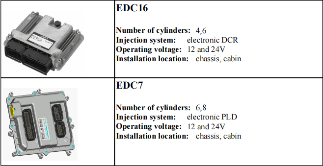
With the start-up of the Deutz Tier lll engines the engine management system EMR3 will be used with the control units EDc16 and EDC7.
For the DCR (DEUTZ Common Rail System for TcD2012, TCD2013) the EDc16 is used as the standard control system, for the PLD system (pump-line-nozzle system for TCD2015) the EDC7. Both systems allow a precise control of the fuel injection depending on the engine operating parameters.
They contain functions which are necessary for achieving a high system security level and the required exhaust quality.
Related Contents:
Functional description EMR3
The control units EDC 16 / EDC 7 are compatible with the EMR2 with regards to the interface
functions. The following standard functions are provided:
ambient pressure-depending filling limit
monitoring and engine protection functions: fuel filter, fuel pre-pressure,
charge air temperature, rail pressure, oil pressure, coolant temperature, speed engine stop by switch
In addition to this the following optional functions are provided control of starter with start procedures (restart lock etc.)
speed control/limitation
Multiple State Switch 1 (up to 4 fixed speeds selectable)
Multiple State Switch 2 (up to 4 torque curves selectable)
extendable monitoring and engine protection functions: coolant level, air filter differential
pressure and two further temperatures for customer application (e.g. gear oil temperature)
extended test functions engine brake control override function (delay of engine shutdown)
automatic engine shutdown (engine protection) or only shutdown request (for special applications)
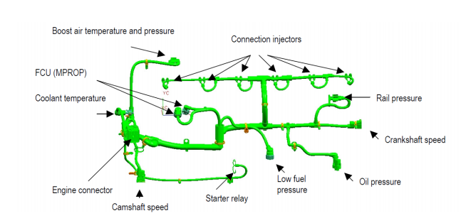
System elements EMR3
The EMR 3 system consists of at least these elements:
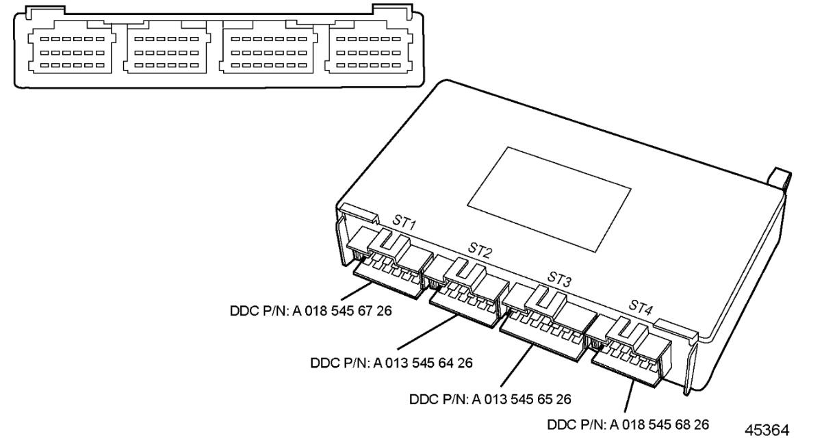
control unit
speed sensors for the crankshaft and the camshaft
rail pressure sensor, rail pressure control valve (MPROP)
temperature sensor(coolant)
combined charge air pressure and charge air temperature sensor
oil pressure sensor
ambient pressure sensor (integrated in the control unit)
speed setpoint transmitter, accelerator pedal
signal light for warning, diagnostics, error message etc.
diagnosis button
engine wire harness and vehicle wire harness
monitoring fuel pre-filter (water in fuel)