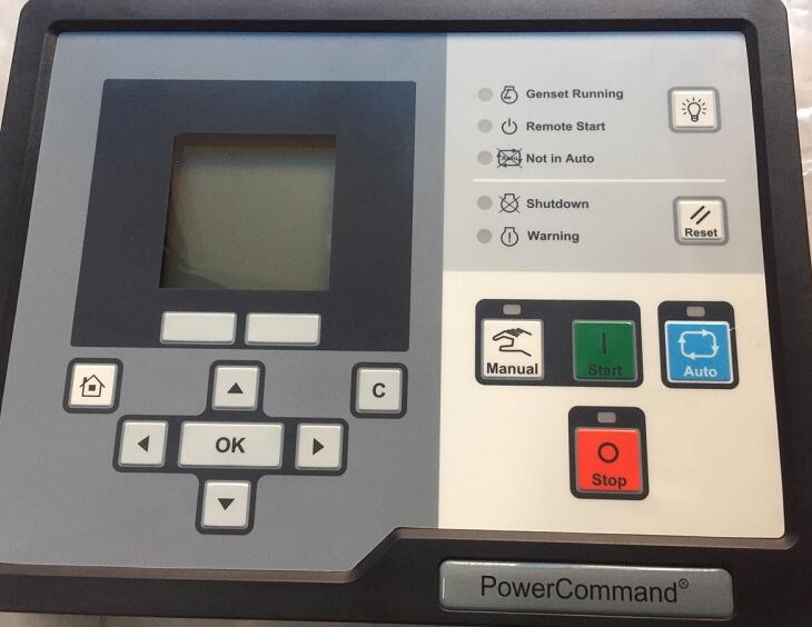
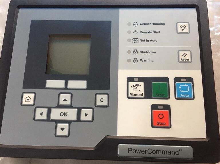
Posted on

PCC1302 PowerCommand Code 781 – ECM CAN Datalink Has Failed

Logic:
Communication between the engine control module (ECM) and the generator set control is severed.

PCC1302 Command

Preparations:

2023 Cummings InPower 14.5 Pro

PowerCommand Diagnostic 9 Pin Adapter Cable for InPower


Possible Causes:
1. The Engine ECM has lost power or failed
2. The CAN datalink has failed

Diagnosis and Repair:
1. The Engine ECM has lost power or failed
a. Check the wiring from the base board.
b. Keyswitch control relay is a normally open relay. Ensure that B+ is available at the relay input, then measure the voltage output. If there is a B+ at both the input and
output of the Keyswitch control relay, the relay is not faulty. If B+ is noted at the input but not at the output of the Keyswitch control relay, replace the relay.
c. Connect to the engine ECM with InPower and/or Insite, to verify that the ECM is functioning properly and is communicating with the CAN-LINK network. Refer to the
engine service manual for ECM troubleshooting procedures, if the ECM is faulty,replace.
2. The CAN datalink has failed
a. There is a defective datalink harness connection, or open circuit; inspect the datalink harness and connector pins. Also check the shield ground connection.

b. Check the terminating resistors. With connector disconnected from the base board and the engine datalink connection disconnected from the ECM control, measure
resistance between pins (60 ohms is satisfactory). If the resistance is not 60 ohms,check the terminating resistors. Each of the two terminating resistors should be 120
ohms, replace if not 120 ohms.

Posted on

PCC1302 Command Code 426 – J1939 Data Link Cannot Transmit Solution

PCC1302 Command

This instruction show you guide on how to solve PCC1302 Command trouble code 426 J1939 Data link cannot transmit.

PCC1302 Command

Preparations:

2023 Cummings InPower 14.5 Pro


Logic:
Communication between the ECM and another device on the SAE J1939 data link has been lost.

Possible Causes:
1. Communication error

2. Faulty engine harness

Diagnosis and Repair:
1. Communication error
a. Check for ECM communication with InSite.
a. Connect the INLINE data link adapter to SAE J1939 data link diagnostic connector.
b. Attempt to communicate with the ECM using InSite.

2 Faulty engine harness
a. Inspect the engine harness and the connector pins.

a. Disconnect the engine harness connector from the extension harness.
b. Inspect for corroded pins, bent or broken pins, pushed back or expanded pins.
c. Inspect for evidence of moisture in or on the connector.
d. Inspect for missing or damaged connector seals.
e. Inspect for dirt or debris in or on the connector pin.

Posted on

PCC1302 Command Code 195 Coolant Level Sensor ORR High Warning Repair

PCC1302 Command

PCC1302 Command fault code 195 engine Coolant level sensor signal is out of range – shorted high.
PCC1302 Command

Related Contents:

2023 InPower 14.5 Service Tool Diagnostic Software+INCAL 2023.06

Cummings INLINE6 Diagnostic Kit


Possible Causes:
1. Faulty coolant level sensor connections
2. Faulty coolant level sensor
3. Faulty engine harness
4. Faulty extension harness

NOTICE

Part Number 3822758 – Male Deutsch/AMP/Metri-Pack test lead

Part Number 3822917 – Female Deutsch/AMP/Metri-Pack test lead


Diagnosis and Repair:
1. Faulty coolant level sensor connections
a. Inspect the coolant level sensor and the harness connector pins.
a. Disconnect the engine harness connector from the coolant level sensor.
b. Inspect for corroded pins, bent or broken pins, pushed back or expanded pins.
c. Inspect for evidence of moisture in or on the connector.
d. Inspect for missing or damaged connector seals.
e. Inspect for dirt or debris in or on the connector pins.

  1. Faulty coolant level sensor
    a. Check the resistance of the sensor
    a. Disconnect the engine harness connector from the coolant level sensor.
    b. Measure the resistance between the coolant level sensor signal pin and the coolant level sensor return pin.
  2. Faulty engine harness
    a. Inspect the engine harness and the extension harness connector pins.
    a. Disconnect the engine harness from the extension harness.
    b. Inspect for corroded pins, bent or broken pins, pushed back or expanded pins.
    c. Inspect for evidence of moisture in or on the connector.
    d. Inspect for missing or damaged connector seals.
    e. Inspect for dirt or debris in or on the connector pins.
  3. Check for a short circuit from pin to pin.
    a. Disconnect the engine harness connector from the extension harness.
    b. Disconnect the engine harness from the coolant level sensor.
    c. Disconnect the engine harness from all sensors that have a shared return with the coolant level sensor. Measure the resistance from the intake manifold temperature return pin on the engine harness inline connector to all other pins in the engine harness inline connector.
    d. Measure the resistance from the coolant level sensor signal pin on the engine harness inline connector to all other pins in the engine harness inline connector.
    e. If all measurements are greater than 100k Ohms, then the resistance is correct.
  4. Check for an open circuit.
    a. Disconnect the engine harness connector from the extension harness.
    b. Disconnect the engine harness from the coolant level sensor. c. Measure the resistance from the coolant level sensor return pin on the engine harness inline connector to the coolant level sensor return pin at the engine harness sensor connector.
    d. Measure the resistance from the coolant level sensor signal pin on the engine harness inline connector to coolant level sensor signal pin at then engine harness sensor connector.
    e. If the measurement is less than 10 ohms, then the resistance is correct.
  5. Faulty extension harness
    a. Inspect the extension harness pins.
    a. Disconnect the extension harness.
    b. Inspect for corroded pins, bent or broken pins, pushed back or expanded pins.
    c. Inspect for evidence of moisture in or on the connector.
    d. Inspect for missing or damaged connector seals.
    e. Inspect for dirt or debris in or on the connector pins.
  6. Check for an open circuit.
    a. Disconnect the extension harness from the engine harness.
    b. Measure the resistance from the intake manifold temperature return pin on the
    extension harness connector to the intake manifold temperature return pin at the
    extension harness inline connector.
    c. Measure the resistance from the coolant level sensor signal pin on the extension
    harness connector to the coolant level sensor signal pin at then engine harness
    inline connector.
  7. Check for a short circuit from pin to pin.
    a. Disconnect the extension harness from the engine harness.
    b. Measure the resistance from coolant level sensor return pin on the extension harness connector to all other pins in the extension harness connector.
    c. Measure the resistance from the coolant level sensor signal pin on the extension harness connector to all other pins in the extension harness connector.
    d. If all measurements are greater than 100k ohms, then the resistance is correct.
Posted on

PCC1302 Command Code 155 Intake Manifold Temperature High Shutdown

PCC1302 Command

PCC1302 Command controller engine intake manifold temperature has exceeded 203° F (95° C) for greater than 10 seconds.It set fault code 155,intake manifold temperature high and machine shutdown,here show how to solve it.

PCC1302 Command

2023 InPower 14.5 Service Tool Diagnostic Software+INCAL 2023.06

Cummings INLINE6 Diagnostic Kit


Possible Causes:
1. High ambient temperature
2. Radiator blocked
3. Louvers are closed or damaged
4. Charge air cooler fins or radiator fins are damaged or obstructed
5. Fan belt is broken or loose
6. Fan drive or fan controls are malfunctioning
7. Inaccurate coolant temperature sensor
8. Fault simulation feature is enabled
9. Incorrect threshold setting

Diagnosis and Repair:
1 High ambient temperature
a Using thermocouple verify air temperature entering intake louver of generator.
b Reduce loads or recirculation of discharge air to generator in elevated ambient.

2 Radiator blocked
a Inspect radiator for debris or blockages.
b Remove blockage or winterfront as applicable.

3 Louvers are closed or damaged
a Inspect louvers for proper operation.
b Repair or replace if damaged.
c Check louver motor for proper operation.
d If louver motor is operational, verify louver shutter thermostat is operational


4 Charge air cooler fins or radiator fins are damaged or obstructed
a Inspect for dirt, debris or obstructions.
b Clean if necessary.

5 Fan belt is broken or loose
a Inspect for dirt, debris or obstructions.
b Clean if necessary.

6 Fan drive or fan controls are malfunctioning
a Inspect for dirt, debris or obstructions
b Clean if necessary.
7 Inaccurate coolant temperature sensor
a Use a thermocouple or similar device to measure coolant temperature near sender and compare to coolant temperature displayed.
b Verify the temperature sender resistance and compare to specifications called out in the engine manual.
c Verify continuity from temperature sender wire to engine ECM. Harness resistance should be less than 5 Ohms.
d Repair or replace faulty components or wiring.

8 Fault simulation feature is enabled
a Use the service tool to connect to the engine ECM and verify fault override toggle is disabled.
b Reconfigure generator and disable fault overrides.

9 Incorrect threshold setting
a Use the service tool to connect to the engine ECM and verify fault threshold settings and compare to the specifications called out in the engine manual.
b Verify ECM and PCC calibration number and revision is correct.
c Recalibrate the engine ECM to reset the threshold settings.