This instruction show you guide on how to repair Doosan excavator machine P2035 DPF (SCRF) inlet temperature drift fault.
Preparations:
2025 Doosan Data Monitoring System DMS-5
2024 Doosan Diagnostic Software Full Package
Doosan uVIM Diagnostic Tool
1 Overview
“E” SPNFMI
E00324220
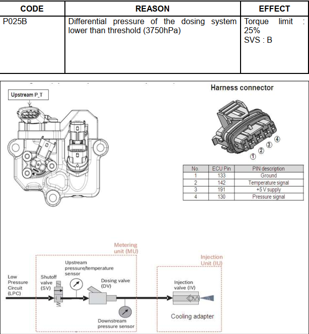
REASON:
1 Electrical problem (DPF(SDPF) in temperature sensor connector)
2 Tampering (DPF(SDPF) in temperature sensor is not installed well for tampering, reduced DEF consumption)
3 Electrical problem (Faulty DPF(SDPF) in temperature sensor)
EFFECT:
CE lamp ON Torque Reduction 1(Mild) DPF regeneration inhibit by Active and Forced
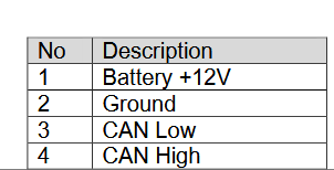
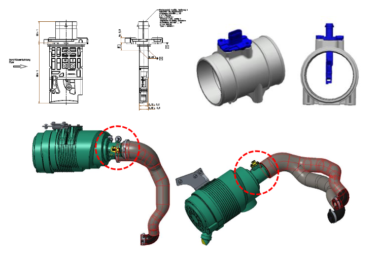
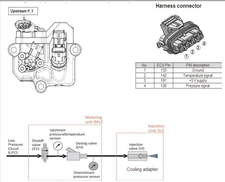
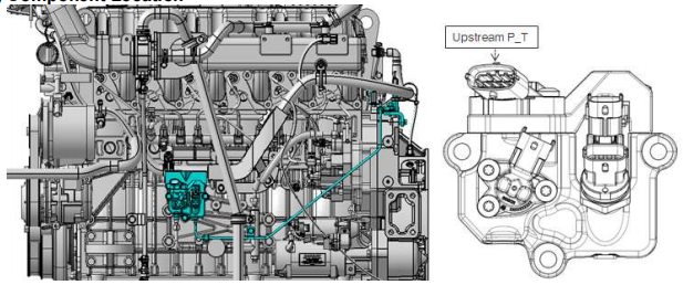
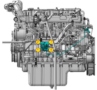
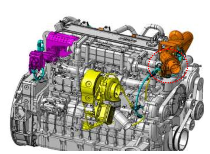
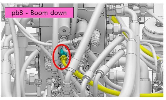
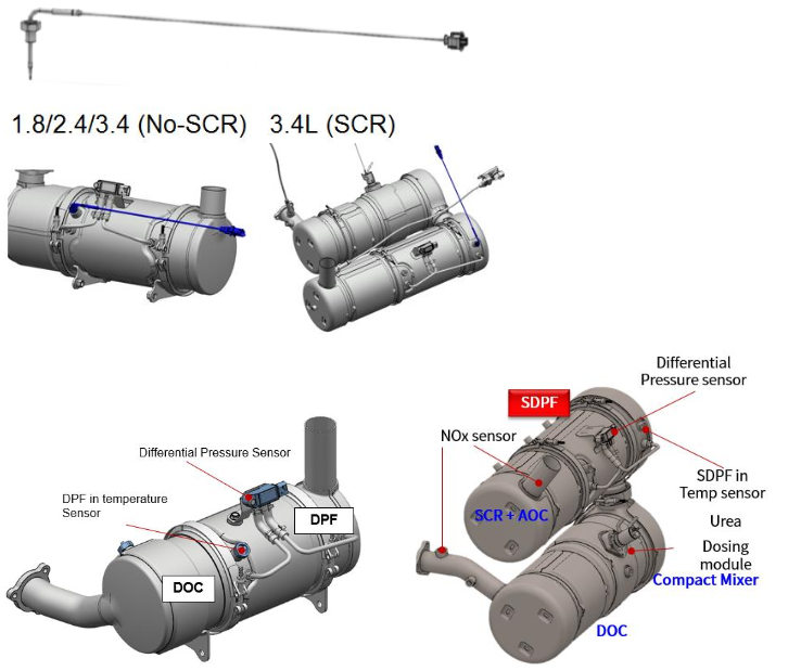
2 Component Location
3 Condition for Running Diagnostic
Engine key on after 12hrs soaking.
* The engine soaking time is calculated based on real timer from CAN signal of machine
controller or GPS. And this fault diagnosis is only performed when the CAN signal is valid.
4 Condition for Setting the Fault Code
The DPF(SCRF) in temperature is compared with all other temperature sensors (Inlet air,
Intake manifold, Turbine in, Coolant) at 12hrs soaking condition and if the difference of value
is higher than all other sensors, fault code is raised. (>20degC)
* DPF regeneration is inhibited because the value of the DPF (SCRF) inlet temperature sensor
is not valid.
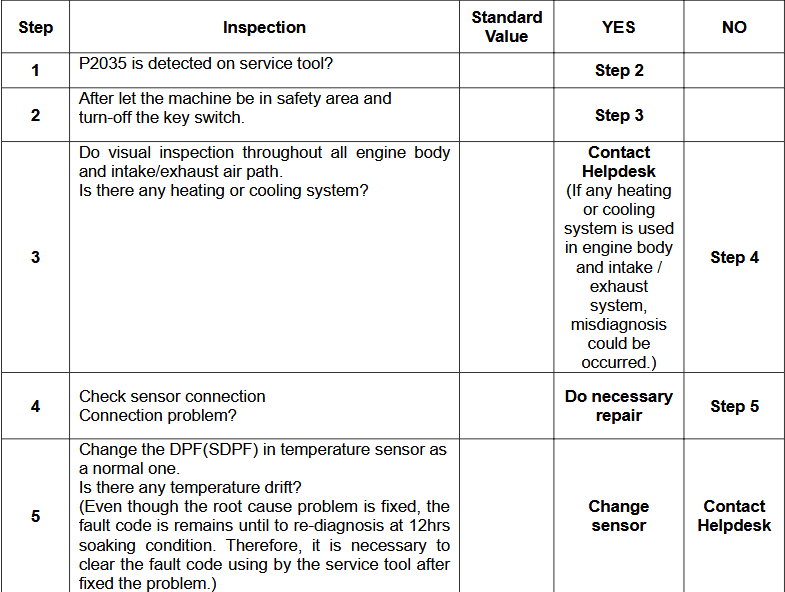
* If any heating or cooling system is used in engine body and intake / exhaust system, misdiagnosis could be occurred. Therefore, first check if there is a cause of temperature
change when engine soaking condition. (Heating system, Cooling system, etc…)
5) Condition for Clearing the Fault Code
DPF(SDPF) inlet temperature is within normal operation range.
* Even though the root cause problem is fixed, the fault code is remains until to re-diagnosis at
12hrs soaking condition. Therefore, it is necessary to clear the fault code using by the service
tool after fixed the problem.
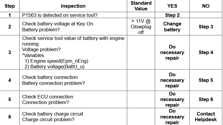
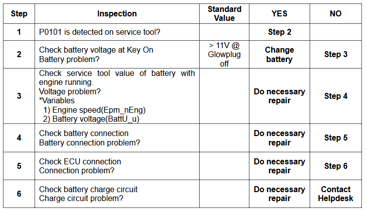
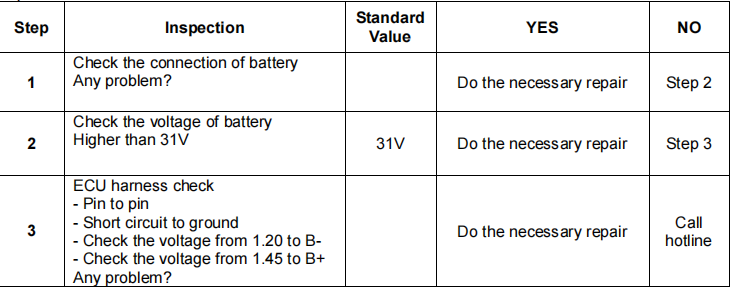
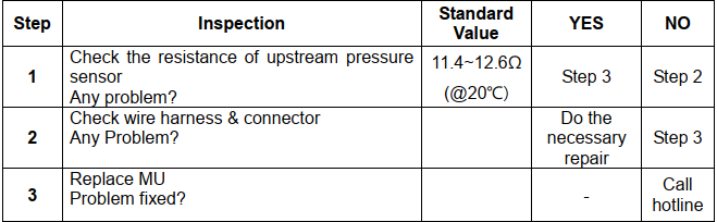
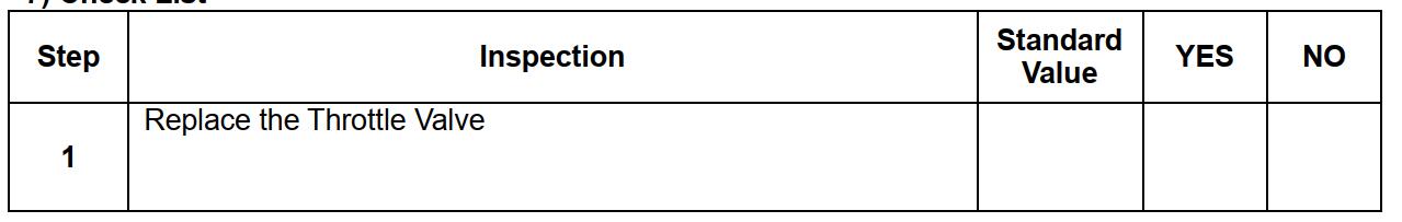
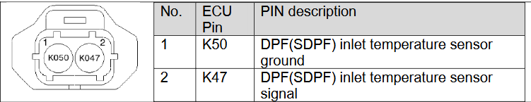
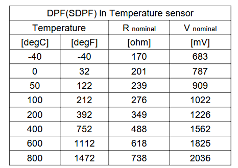
6 Check List