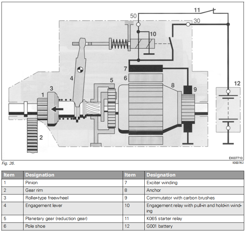
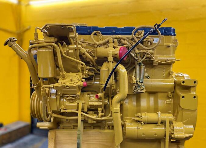
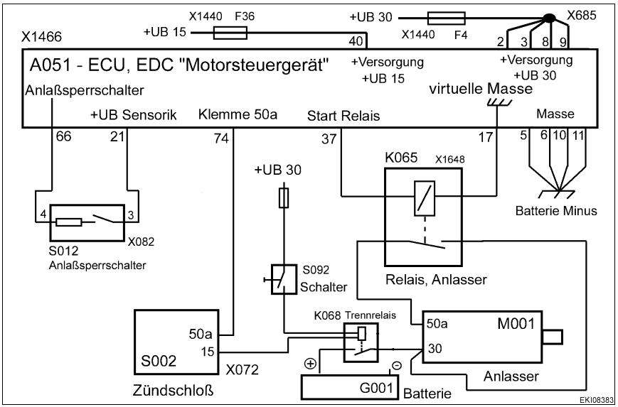
Posted on

Volvo EC500F L5 Excavator Engine Belts Replacement Guide

Volvo EC500F L5 Excavator Engine Belts Replacement Guide (2)

It is necessary to replace a new belts when it broken or some related problem occurs,here autoepccatalog.com show you guide on how to do it.


Related Contents:

Volvo PROSIS Offline R4 2023.12

Volvo VOCOM 88890300

Volvo Techtool 2.8.230


Procedures:

1.Place the machine in the service position B

2.Open the engine hood.

3.Turn the belt tensioner clockwise using a ratchet hand tool and remove the engine drive belt.

NOTE!

The belt adjuster tension is very strong. Therefore pay attention to prevent injury after removing belt.

NOTE!

Lock the belt tensioner pulley with a pin ø5 mm (0.2 in) when removing the belt.

4.Turn the belt tensioner clockwise using a ratchet hand tool and remove the alternator/compressor belt.

NOTE!

The belt adjuster tension is very strong. Therefore pay attention to prevent injury after removing belt.

NOTE!

Lock the belt tensioner pulley with a pin ø5 mm (0.2 in) when removing the belt.

5.Install the new engine drive belt and alternator/compressor belt.

6.Close the engine hood.

Posted on

QSK CM2358 Fault Code 123 Pressure Sensor Circuit Voltage Low Error

QSK CM2358 Fault Code 123 Intake Manifold 1 Pressure Sensor Circuit – Voltage Below Normal or Shorted to Low Source.Low signal voltage or open circuit detected in the intake manifold pressure sensor circuit.Possible reduced engine performance.


Related Contents:

Insite 8.9.2/8.7 Diagnostic for Cummings Engine

Cummings INLINE 6 Diagnostic Adapter for Heavy Duty Truck High Quality


Circuit Description

The engine control module (ECM) provides a 5 volt supply to the intake manifold pressure sensor on the sensor supply circuit. The ECM also provides a ground on the sensor return circuit. The intake manifold pressure sensor provides a signal to the ECM on the intake manifold pressure sensor signal circuit. This sensor signal voltage changes based on the pressure in the intake manifold.


Component Location

The intake manifold pressure sensor 1 is located in intake manifold 1.

Conditions for Running the Diagnostics

This diagnostic runs continuously when the keyswitch is in the ON position.


Conditions for Setting the Fault Codes

The Engine Control Module (ECM) detected the intake manifold pressure sensor signal voltage is out of range low.


Action Taken When the Fault Code is Active

The ECM illuminates the amber CHECK ENGINE lamp immediately when the diagnostic runs and fails. A default value of the intake manifold pressure reading is used.


Conditions for Clearing the Fault Code

Turn the keyswitch OFF. Allow the ECM to completely power down and turn the keyswitch ON.

The fault code status displayed by the recommended electronic service tool or equivalent will change to INACTIVE immediately after the diagnostic runs and passes.

The ECM will turn off the amber CHECK ENGINE lamp immediately after the diagnostic runs and passes.

The “Reset All Faults” command in the recommended electronic service tool or equivalent can be used to clear active and inactive faults.


Shop Talk

The intake manifold pressure sensor shares supply and return wires in the engine harness with other sensors. Opens and shorts in the engine harness can cause multiple fault codes to be active. Before troubleshooting Fault Code 123, check for multiple faults.


Possible causes of this fault code include:

Signal circuit open or shorted to ground in the engine wiring harness or sensor.

Supply wire open or shorted to ground.

A malfunctioning intake manifold pressure sensor

Posted on

JPRO Wheel Speed Chart Test or Wheel Speed Window Test

JPRO Wheel Speed Chart Test or Wheel Speed Window Test

The Wheel Speed Window test is available for any tractor and trailer braking system that report wheel speed data.
This test can be used to verify and test wheel speed sensors and confirm fault codes before and after a repair or replacement.


Related Contents:

JPRO Noregon Commercial Fleet Diagnostics 2023

Noregon JPRO DLA+ 2.0 Adapter


Procedures:
1Select Wheel Speed Chart Test or the Wheel Speed Window Test and press Enter or press Start Button.
2The test dialog will be displayed.

JPRO Wheel Speed Chart Test or Wheel Speed Window Test

3Lift the suspect axle(s) to allow free spinning wheel(s). While looking at the test screen, spin the wheel(s) to
check for changes in the graph or digital readout to match the wheel being spun.
4Click Diagnostic Info to view additional diagnostic information related to wheel speed readings.
5Press Exit button when ready to exit this test and return to the test selection dialog.

Posted on

PCC1302 PowerCommand Code 781 – ECM CAN Datalink Has Failed

Logic:
Communication between the engine control module (ECM) and the generator set control is severed.

PCC1302 Command

Preparations:

2023 Cummings InPower 14.5 Pro

PowerCommand Diagnostic 9 Pin Adapter Cable for InPower


Possible Causes:
1. The Engine ECM has lost power or failed
2. The CAN datalink has failed

Diagnosis and Repair:
1. The Engine ECM has lost power or failed
a. Check the wiring from the base board.
b. Keyswitch control relay is a normally open relay. Ensure that B+ is available at the relay input, then measure the voltage output. If there is a B+ at both the input and
output of the Keyswitch control relay, the relay is not faulty. If B+ is noted at the input but not at the output of the Keyswitch control relay, replace the relay.
c. Connect to the engine ECM with InPower and/or Insite, to verify that the ECM is functioning properly and is communicating with the CAN-LINK network. Refer to the
engine service manual for ECM troubleshooting procedures, if the ECM is faulty,replace.
2. The CAN datalink has failed
a. There is a defective datalink harness connection, or open circuit; inspect the datalink harness and connector pins. Also check the shield ground connection.

b. Check the terminating resistors. With connector disconnected from the base board and the engine datalink connection disconnected from the ECM control, measure
resistance between pins (60 ohms is satisfactory). If the resistance is not 60 ohms,check the terminating resistors. Each of the two terminating resistors should be 120
ohms, replace if not 120 ohms.

Posted on

How to Use CAT ET Service Tool Auto Retarder Test Function

Caterpillar ET Service Tool diagnostic software Auto Retarder Test function allows the operation of the Auto Retarder Control (ARC) system to be verified while the machine is stationary. The ARC outputs are activated and monitored for correct operation.


Related Contents:

Caterpillar CAT ET 2023C 2022A Service Tool

Caterpillar 18 Digits Factory Password

Cat Com 3 adapter 478-0235

CAT SIS 2021 EPC+Service Manual


Accessing

To run the Auto Retarder Test function, select “Diagnostic Tests” from the Diagnostics menu, and then select “Auto Retarder Test” from the submenu. The Auto Retarder Test will be displayed.


Screen Layout

The Auto Retarder Test screen has the following areas:


Display Area

The Auto Retarder Test display area has three columns:

Description – Provides the name of the parameter set to run the test

Required Condition – Displays the value that the parameter must meet in order to run the test.

Actual Value – Displays the actual value of the required condition parameters.


Status Parameter Area

The Auto Retarder Test status parameter area lists parameters and their current values. The ARC Control Solenoid displays the position in percentage of the ARC Control Solenoid. The ARC Pressure Switch Status displays if the status is “High” or “Low.”


Status Line

The Auto Retarder Test status line displays if the test is “On” or “Off.”


Buttons

The buttons available in the Auto Retarder screen are:

Start – Click to start the test. When clicked, “On” will be displayed in the status line, and the button will be disabled until the test is stopped.

Stop – Click to stop the test. When clicked, “Off” will be displayed in the status line, and the button will be disabled until Start is clicked again.

Posted on

Misubishi Diesel Engine D04EG Cylinder Head Assembly

Misubishi Diesel Engine D04EG Cylinder Head Assembly

When removing the cylinder head gasket, be careful not to damage the cylinder head or crankcase surface with a screwdriver or the like.

Misubishi Diesel Engine D04EG Cylinder Head Assembly

Related Contents:

Mitsubishi V.C.I Diagnostic Kit

Mitsubishi EngineScope Diagnostic Software


Procedures:

(1) Lift up the cylinder head assembly, and remove the cylinder head assembly from the crankcase.
Note: If the cylinder head assembly cannot be removed due to crimping of the cylinder head gasket, tap the thick area on the side of the cylinder head using a plastic hammer to give a shock.
Do not lift up the crankcase by yourself. Use a crane or lift it up by two persons.
(2) Remove the cylinder head gasket.
Note: If there is a cylinder head problem, check the bolts for tightness with a torque wrench before removing the cylinder head bolts.

Posted on

How to Use Nexiq eTechnician Full Report to View Diagnostic Report

How to Use Nexiq eTechnician Full Report to View Diagnostic Report (1)

Nexiq eTechnician allow you use the Full Report tab to view and customize diagnostic reports for the vehicle to which you are connected. You can customize the report by selecting the items you want to include. Place a check mark in the box next to the item you want to select.


What You Need?

Nexiq USB Link 2 Diagnostic Tool

2023 Nexiq eTechnician 2.8/2.1 Diagnostic Software

  • Report Content
    All Data (use this check box to include all data for all components)
  • Components
    Engine
    Brakes
    Transmission
  • Data Types
    Faults
    Live Data
    Trip Data

NOTE:
i You can further customize your reports by adding a header that includes your company information and/or logo.  
 
You use the Settings screen to add or update this information.
The date of the report is included at the bottom of the report in the footer.
To view a diagnostic report for the vehicle:
1 Click on the Full Report tab on the right side of the screen

The Full Report screen is displayed.

How to Use Nexiq eTechnician Full Report to View Diagnostic Report (1)

2 Use the scroll bar on the right side of the screen to scroll down through the information.
3 Use the check boxes to change the data included on the report (e.g., deselect
Trip Data to remove it from the report).
4 Click Update.
5 To add header including company information, click the Settings icon

The Settings screen is displayed.

How to Use Nexiq eTechnician Full Report to View Diagnostic Report (2)

6 Use the text-entry boxes to add your company information.
You can use the Tab key to navigate to the next text-entry box
NOTE:
i You can also add a company logo, or another suitable image. Use the Logo box to select and download the desired image.
7 When you have finished adding your information, click on the Full Report tab to go back to your report.

The report is generated, including the company information you added.

How to Use Nexiq eTechnician Full Report to View Diagnostic Report (3)

8 Click Print to send your report to a printer.
NOTE:
i If you are not connected to a printer, you can save the information to a file in the location of your choice.
9 When you are finished generating reports, click on the Summary tab to go back to the Summary screen

Posted on

DetroitGHG14 Idle Will Arm but Will not Restart Engine Solution

This instruction show you guide on how to solve/optimize idle will arm but will not restart the engine for Detroit EPA07 GHG14 DDEC VI 10.


Preparations:

DDDL 8.18 2023

Nexiq USB Link 2 Adapter


Procedures:

Check as follows:

1 Is MCM fault code SPN 1663 /FMI 7 present?

1aYes; troubleshoot this code first.

1b No; Go to step 2.


2 Was the CPC recently programmed?

2a Yes; check for proper CPC parameter settings. Refer to section “Optimized Idle” of the A&I Manual (See table below).

2b No; Go to step 3.


3 Using DiagnosticLink, verify the operation of the Optimized Idle Safety Loop and the Vehicle Speed Sensor (VSS). Under Instrumentation, go to the Chart tab and select the following on the chart:


  • DSL: Parking Brake
  • DSL: Hood Tilt Switch
  • DSL: Neutral Switch
  • ASL: Road Speed

Cycle each switch and monitor their functionality. Monitor the Road Speed; it should read zero when the vehicle is stationary.

Was a fault with either the Optimized Idle Safety Loop or VSS found?

3a Yes; repair as necessary.

3b No; Go to step 4.


4 Is the vehicle equipped with an Auxiliary Power Unit (APU) or ParkSmart?

4a Yes; vehicles with an APU or ParkSmart may not use Optimized Idle to control the cab temperatures. If this is the customer’s complaint, refer to the APU or ParkSmart operation instructions.

4b No; Go to step 5.


5 Check the Optimized Idle Thermostat settings; Refer to section “Thermostat Operation” of the Optimized Idle User Manual (DDC-SVC-MAN-0019) . Is the Optimized Idle Thermostat properly configured?

5a Yes; install a test CPC. Go to step 6.

5b No; Refer to section “Thermostat Operation” of the Optimized Idle User Manual (DDC-SVC-MAN-0019) . Verify repair.


6 Will Optimized Idle work correctly with the test CPC?

6a Yes; replace the CPC.

6b No; Go to step 7.


7 Set the Optimized Idle Thermostat mode to cool the cab and put the vehicle on Optimized Idle mode. Using a heat gun, apply heat to the Optimized Idle Thermostat Skin Temperature sensor; refer to OEM literature for sensor location. Did Optimized Idle start the engine to cool the cab?

7a Yes; Refer to section “Optimized Idle” of the A&I Manual (See table below) for proper Optimized Idle parameter configuration

7b No; Go to step 8.


8.Monitor the Optimized Idle Thermostat temperature reading while applying heat to the sensor. Is the reading on the Thermostat display accurate?

8a Yes; replace the Optimized Idle Thermostat.

8b No; Go to step 9.


9 Disconnect the Optimized Idle Thermostat electrical connector and measure the resistance between pin 3 of the Optimized Idle Thermostat connector, harness side and the sensor ground circuit of the Skin Temperature sensor harness side connector. Is the resistance less than five ohms?

9a Yes; Go to step 10.

9b No; repair the circuit.


10 Measure the resistance between pin 1 of the Optimized Idle Thermostat connector, harness side and the sensor signal circuit of the Skin Temperature sensor harness side connector. Is the resistance less than five ohms?

10a Yes; replace the Optimized Idle Thermostat.

10b No; repair the circuit.

Posted on

How to Delete Configuration File in HINO Truck by HINO DX3

HINO DX3 allows you to delete the file in which the HINO truck ECU setting values are saved.Thsi instruction show you guide o how to use HINO DX3 to delete configuration file.


What You Need?

NEXIQ USB Link 2 Adapter

HINO DX3 2023.07 Diagnostic Software


Procedures:

1 Click or press the [Delete] button.
(Device specification screen)

How to Delete Configuration File in HINO Truck by HINO DX3 (1)

2 Select the file and click or press the [Open] button.
(File selection dialog)

How to Delete Configuration File in HINO Truck by HINO DX3 (2)

3 Click or press the [OK] button in the confirmation message.
(Deletion Confirmation screen)

How to Delete Configuration File in HINO Truck by HINO DX3 (3)

4 Click or press the [OK] button in the confirmation message.
(Deletion Completion screen)

How to Delete Configuration File in HINO Truck by HINO DX3 (4)

Posted on

Perkins 800 Series Industrial Engine Fuel Injector Test

Perform the following procedures in order to determine if a fuel injector does not work correctly.
Bench test the fuel injectors at a temperature of 18° to 20 °C (64° to 70 °F).

What you Need?

Perkins EST 2023A Diagnostic Software

Perkins Communication Adapter 3


Procedures:

1 Run the engine at low idle.
2 Loosen the connection for the high pressure fuel line (1) at the fuel injector on No. 1 cylinder. Do not loosen the nut more than half of a turn. Listen for the low idle to decrease or become rough. Tighten the nut for the fuel supply line on No. 1 cylinder.

Perform this test on each cylinder.
3The fuel injector is faulty when the nut for the fuel supply line is loosened and the following events occur:
• The engine rpm does not decrease.
• The engine does not idle roughly.


4 Remove the fuel injector for additional testing.
Note: If leakage occurs at the nut for the fuel supply line, make sure that the fuel supply line and the nut are correctly aligned with the inlet connection of fuel injector. Do not tighten the nut for the fuel supply line on the high pressure fuel line more than the recommended torque. If the nut is tightened more, the fuel line may become restricted or the threads of the fuel injector and the nut may be damaged.

Cleaning of the fuel injectors
Before a fuel injector is tested, remove any loose carbon from the tip of the fuel injector. Do not use abrasive material or a wire brush in order to clean the nozzle.
The fuel injector is not a serviceable part.

Disassembling or adjusting the nozzle will violate the standards for emissions.
Note: Extra care should be used in handling the fuel injector in order to prevent damage to the nozzle tip.
A scratch or a burr could cause needle leakage or spray distortion. Dirt in the orifices of the nozzle tip can damage engine components. Dirt can also distort the spray pattern of the nozzle.