Posted on

Noregon DLA 2.0 Adapter Error Codes

Noregon DLA 2.0 Adapter Error Codes


704 An invalid buffer parameter was used.
705 The packetization flag should be 1 or 0.
706 Blocking while using window handle notifications is not allowed.
707 One or more of theFilters have an invalid length.
708 The data length for this protocol has been exceeded.
709 The Command buffer is too small.
710 The CAN Bit Timingvalues are invalid.
711 This command is not supported with the current protocol.
712 The J1939 address is no longer valid.
713 Multiple J1939 clients must use same packetizing methods.
714 Device detected but not responding to commands.
716 Anexisting client is connected to the FLASH protocol.
717 ERR_GET_DEVICE_STATUS_FAILED
718 The command failed. The command required to device to be in ‘Boot Mode’.
719 Failed to set device to “Boot Mode’.
720 Failed to set device the starting firmwareaddress.
721 Failed to set the end firmware address.
722 Failed to send ROM data to the device.


723 Failed to manifest device for firmware update.
724 Failed to obtain the device status.
725 The USB interface is in use. Wireless connections is notallowed at this time.
726 The Wireless interface is in use. USB connections is not allowed at the time.
727 Failed to get the protocol connection speed.
728 A DLA+Wireless adapter is not configured for connection.
729 An existing client is connectedto the WIRELESS_CONFIG protocol.
730 ERR_FAILED_TO_START_SERVER
731 ERR_FAILED_TO_CONNECT_TO_SERVER
732 Failed to get the protocol connection speed.
733 Incorrect or invalid firmware version for your DLA+ family adapter.
734 Failed to load theregistry values for your DLA+ family adapter.
735 Failed to load the firmware update files for your DLA+ family adapter.
736 Failed to update the firmware version of your DLA+ family adapter.
737 Failed to read the firmware version of your DLA+ familyadapter.
738 Failed to obtain the device status during firmware update connect.
739 Failed to obtain the device status during firmware perform update.


Posted on

How to Solve Unexpected Loss of Vehicle Speed Signal for Detroit

How to Solve Unexpected Loss of Vehicle Speed Signal for Detroit

This illustration show the guide on how to solve unexpected loss of hard-wired vehicle speed signal.

How to Solve Unexpected Loss of Vehicle Speed Signal for Detroit

What is you need?

2022 Detroit Diesel Diagnostic Link DDDL 8.15 10 Level+12.2021 Troubleshooting


Procedures:

Check as follows:

1 Are there any battery (SPN 168/FMI any) or Controller Area Network (CAN) faults present?

1a Yes; repair those faults first.

1b No; Go to step 2.

2Has the Common Powertrain Controller (CPC) been recently reprogrammed?

2a Yes; ensure the VSS parameters are configured correctly for the vehicle application.

2b No; Go to step 3.

3Is the VSS hardwired?

3a Yes; Go to step 4.

3b No; refer to the vehicle’s electronics and troubleshooting manual for the correct parameter configuration. If configuration is correct, refer to the Original Equipment Manufacturer (OEM) material for J1939 troubleshooting.

4Disconnect the VSS harness connector; refer to OEM literature for location.

5Inspect the VSS harness connector for bent, spread, or corroded pins. Is damage found?

5a Yes; repair as necessary.

5b No; Go to step 6.

6Disconnect CPC connector #3.

7Measure the resistance between pins 13 and 14 of the CPC connector #3. Is the resistance less than 1K ohms?

7a Yes; repair the short between pins 13 and 14 of the CPC connector #3 and the VSS connector.

7b No; Go to step 8.

8Measure the resistance between pin 13 of the CPC connector #3 and the VSS+ harness connector. Is the resistance less than 1K ohms?

8a Yes; repair the wire between pin 13 of the CPC connector #3 and the VSS+ harness connector.

8b No; Go to step 9.

9Measure the resistance between pin 14 of the CPC connector #3 and the VSS- harness connector. Is the resistance less than 1k ohms?

9a Yes; repair the wire between pin 14 of the CPC connector #3 and the VSS- harness connector.

9b No; refer to OEM literature for VSS sensor diagnostics.

Posted on

Detroit EPA07 Engine Motor Control Module

The engine mounted Motor Control Module (MCM) includes control logic to provide overall engine management. more Detroit Diesel you need install 2022 Detroit Diesel Diagnostic Link DDDL 8.15 10 Level+12.2021 Troubleshooting
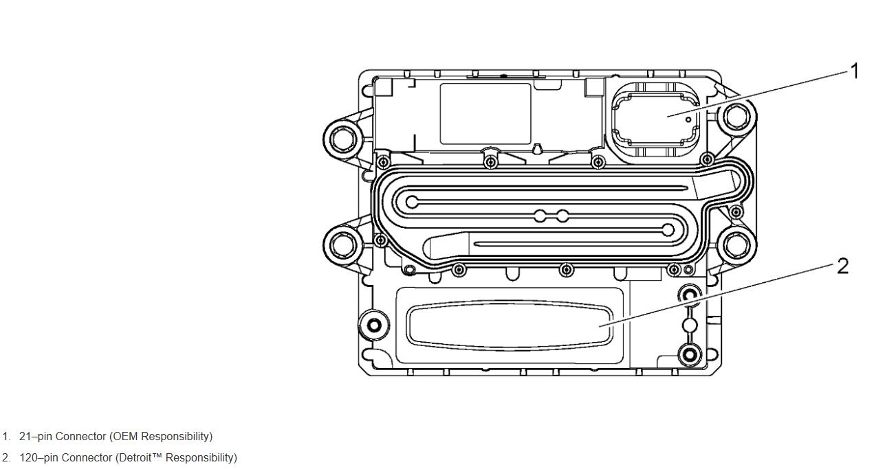
The following is a summary of the tasks the MCM monitors:

Exhaust gas recirculation (EGR)

Intake air preheating system

Turbocharger

Diesel Particulate Filter (DPF) (EPA07 ONLY – for EPA10 the Aftertreatment Control Module (ACM) monitors the DPF)

Instrument cluster

Engine brake

Amplified Pressure Common Rail System (APCRS)

Thermal management

DDEC VI/10 provides an indication of engine and vehicle malfunctions. The MCM continually monitors the DDEC VI/10 system.

Any faults that occur are stored as codes. These codes can be accessed in any of three ways:

A DiagnosticLink ® Standard for DDEC VI/10 can be used to read the codes.

A personal computer (PC) connected to the Motor Control Module (MCM) through a translator device using SAE J1939 Data Link+, are used as the communication link, to Common Powertrain Controller (CPC) and CAN link to Motor Control Module (MCM).

The Amber Warning Lamp (AWL) (check engine) or the Red Stop Lamp (RSL) is illuminated.

The AWL (check engine) (panel mounted yellow indicator light) illuminated diagnose condition as soon as convenient, lights are CPC controlled. The RSL (panel mounted red indicator light) and AWL (check engine) illuminated, a major fault occurred and immediate attention required to avoid engine damage. Automatic engine shutdown or ramp down is available as an option. A shutdown override switch is required to allow the vehicle to be moved to a safe location during automatic shutdown or ramp down. The MCM tells the light when to activate.

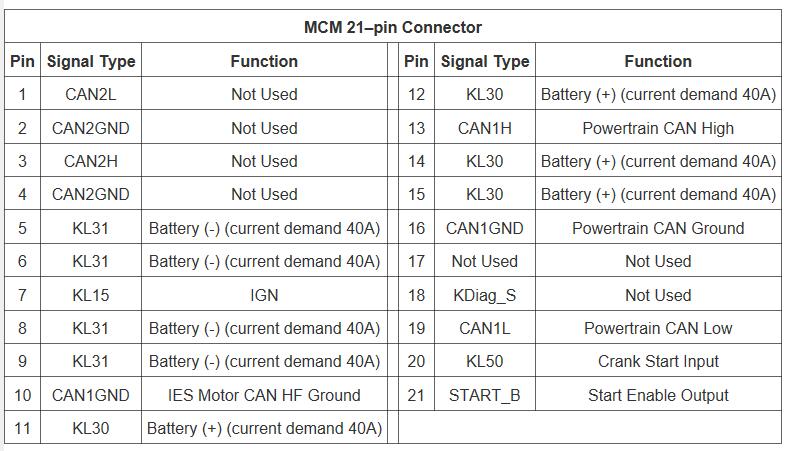
5.2.1 MCM 21–pin Connector

The wiring for the VIH 21–pin to the MCM listed in the following table. The side of the connector shown is looking into the pins.
 

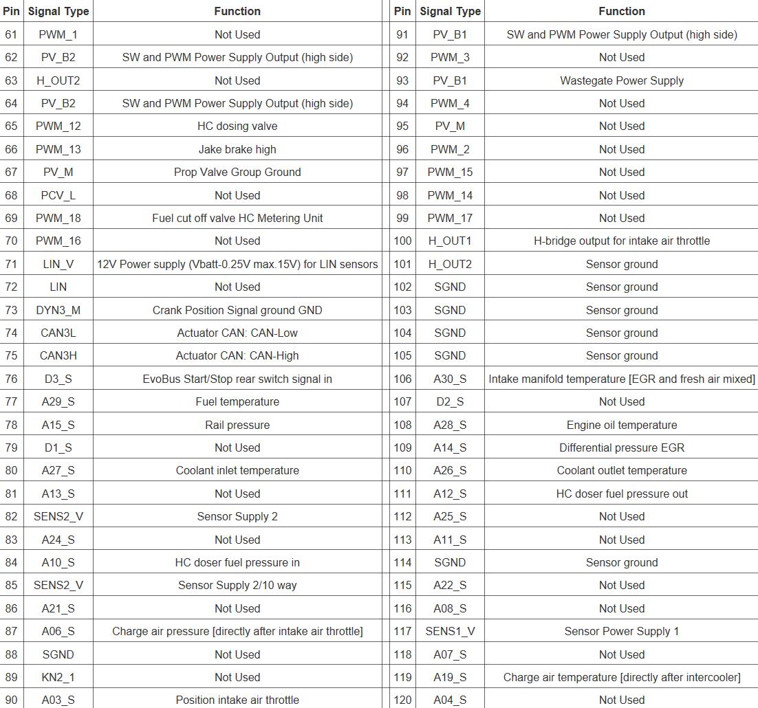
5.2.2 DD13 120-Pin Connector Pin-Out

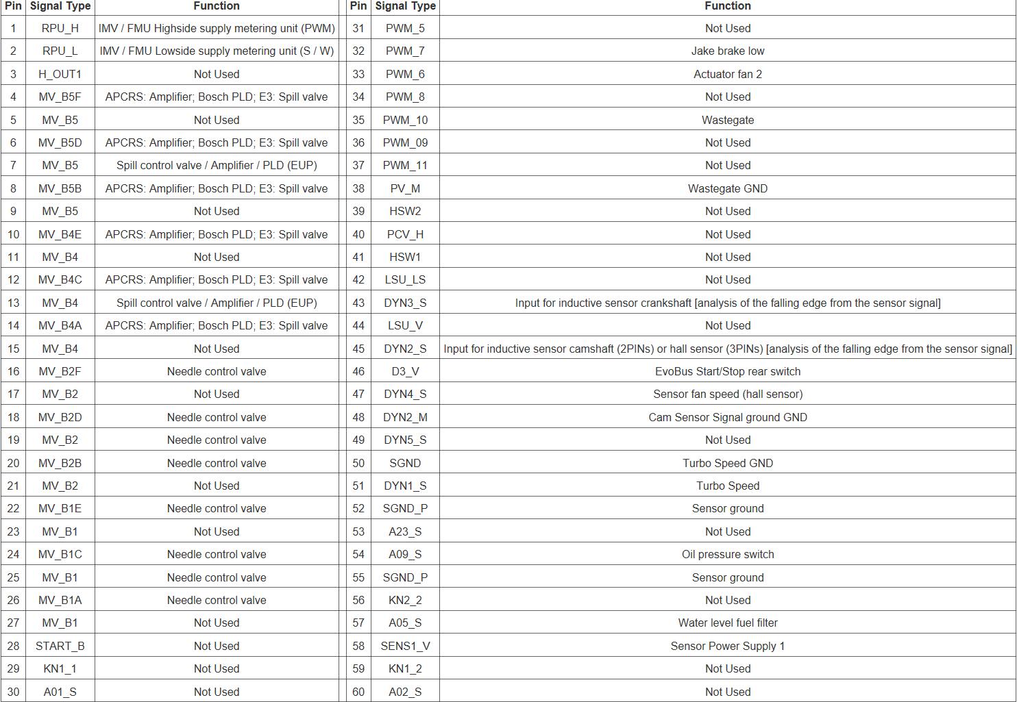
The following tables show the 120-pin connector pin-outs for the DD13 MCM.


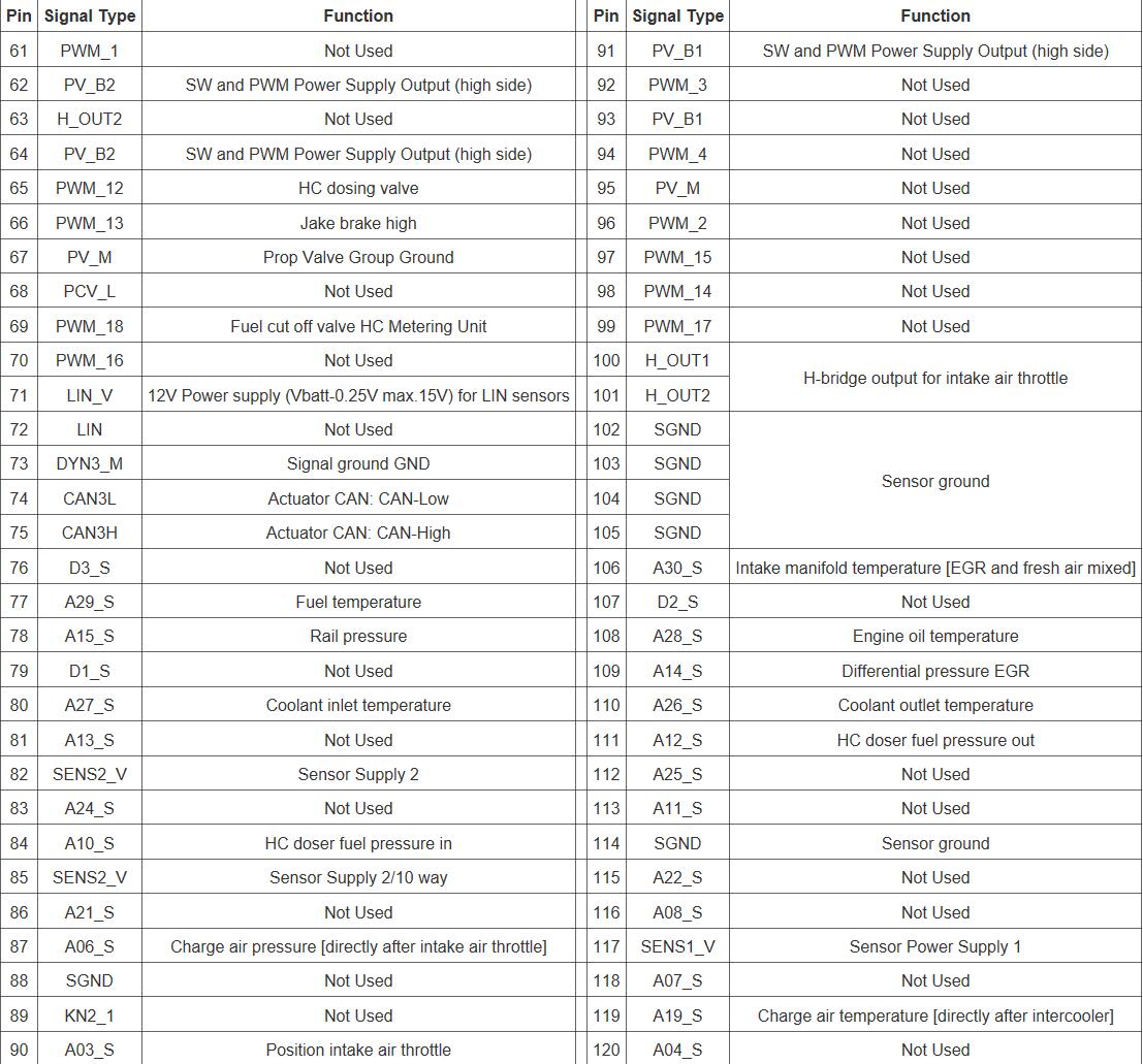
5.2.3 DD15 120-Pin Connector Pin-Out

The following tables show the 120-pin connector pin-outs for the DD15 MCM.
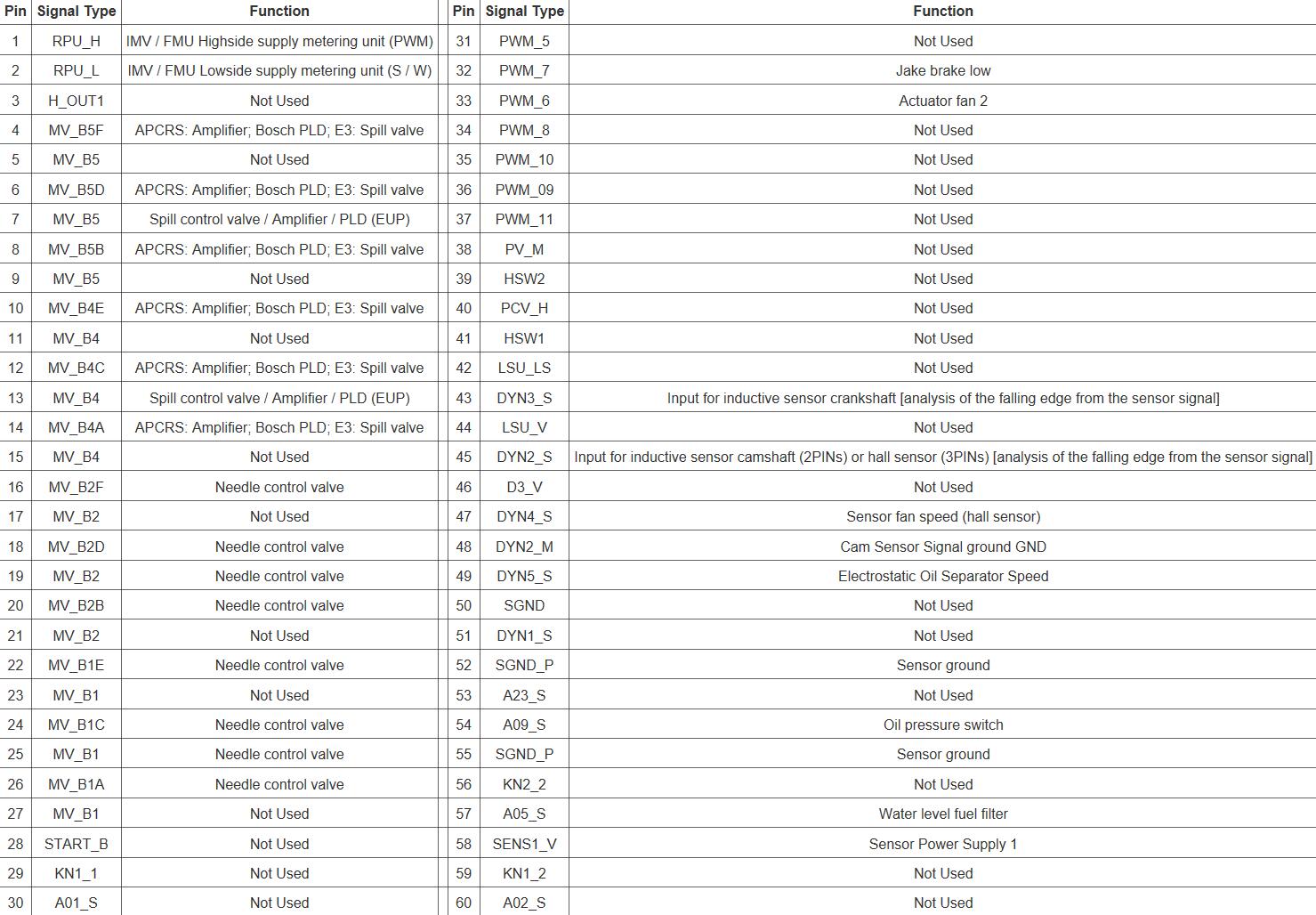
 

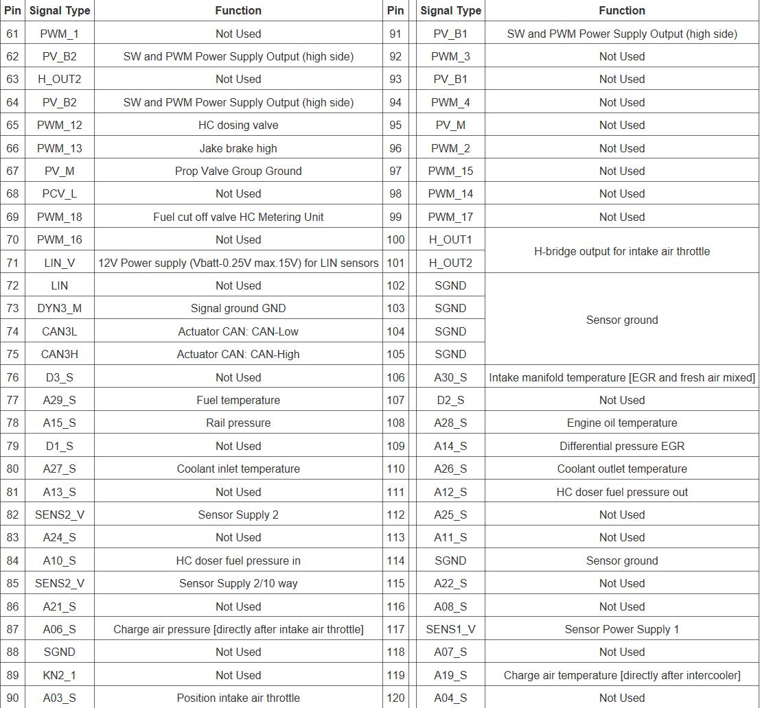
5.2.4 DD16 120-Pin Connector Pin-Out

The following tables show the 120-pin connector pin-outs for the DD16 MCM.
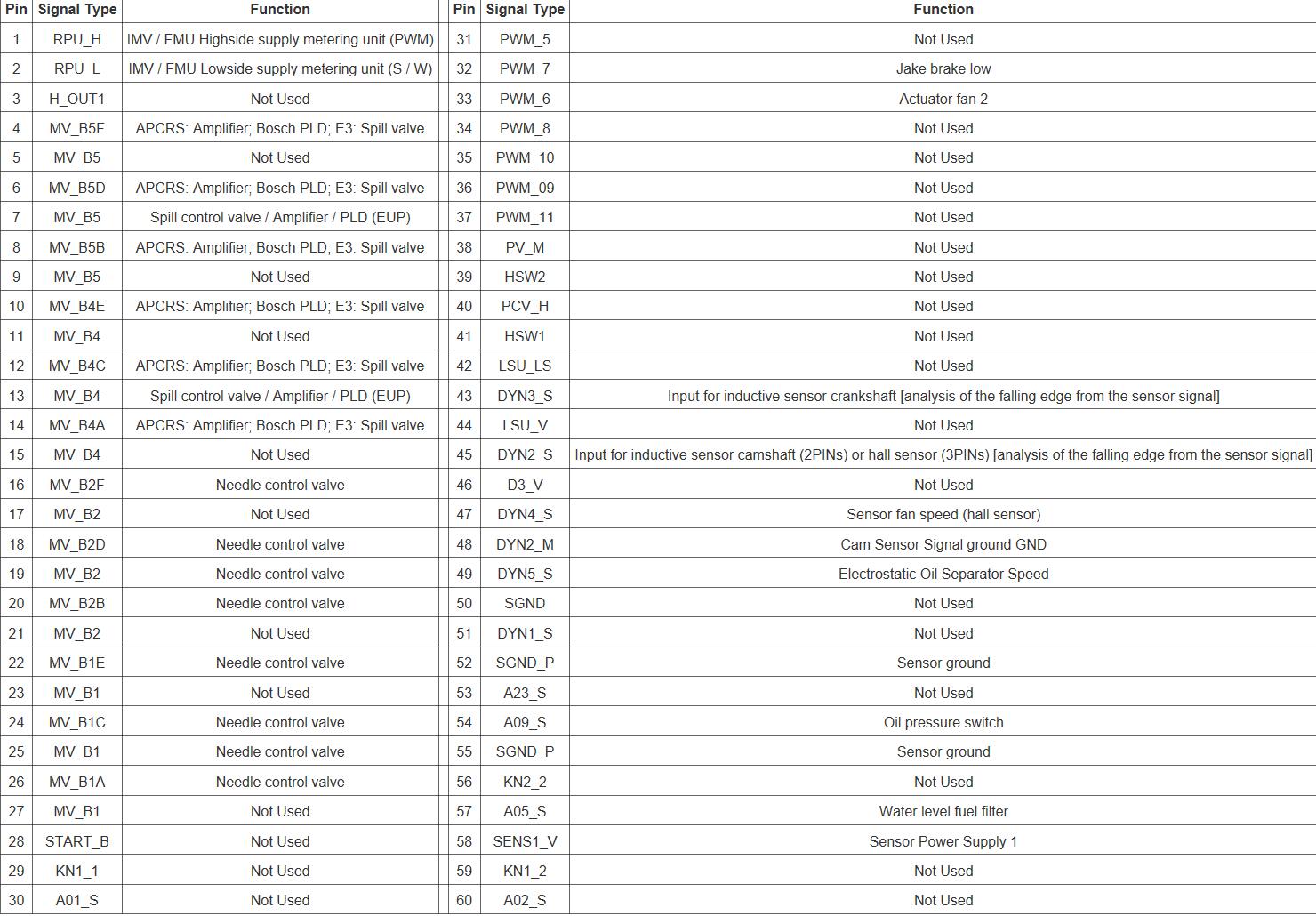
 

5.2.1 Removal of the Motor Control Module

Remove as follows:

1 Release latch on harness connector to remove the 21 and the 120-pin connectors from the Motor Control Module (MCM).

2 Disconnect the vehicle battery power to prevent failure of the MCM.

3 On a rear sump oil pan, disconnect the oil dipstick tube from the MCM.

4 Remove the two vehicle wiring harness retaining bolts.

5 Remove the four bolts holding the MCM to the engine, remove the MCM from engine.


5.2.2 Inspection of the Motor Control Module

Inspect the MCM-MCM2 as follows:

1 Inspect the MCM-MCM2 for damage and replace if required.

2 Inspect the ISO mounts for damage and replace if required.


5.2.3 Installation of the Motor Control Module

Install as follows:

NOTICE

Ensure the MCM metal housing does not come in contact with the chassis.

NOTICE

Ensure MCM is not contaminated with diesel fuel.

Note : If installing a new MCM; after installation, program to proper settings using the programming station.

Note : Do not ground the MCM housing. This can result in false codes being logged.

1 Confirm that vehicle battery power is disconnected and the ignition is in the OFF position.

2 Install the MCM to the engine with four bolts and isolators. Torque the MCM-to-engine bolts to 15 N·m (11 lb·ft).

3 Connect the 21 and 120-pin engine harness connectors to the MCM close and lock latch on the connectors.

4 If equipped with an MCM fuel cooler, install bracket onto fuel line; install bracket and line to MCM with two bolts.

5 If equipped with an MCM fuel cooler install both fuel lines from the MCM to the fuel filter module. Torque bolts to 55 N·m (41 lb·ft).

6 Reconnect vehicle battery power.

7 Turn the ignition to the “ON” position. Observe DiagnosticLink ® Standard for any diagnostic code(s). If any code(s) are logged, refer to the proper code diagnostics.


Posted on

GHG17 Heavy Duty Machine SCR Circuit Diagram

GHG17 Heavy Duty Machine SCR Circuit Diagram,more Detroit Diesel you need install 2022 Detroit Diesel Diagnostic Link DDDL 8.15 10 Level+12.2021 Troubleshooting

1.DEF Tank Screen

2.DEF Line Tank to DEF Pump

3.Pump Electric Motor

4.Ventilation Membrane

5.Freeze Protection Element

6.DEF Pump Suction Port

7.DEF Pump Pressure Port

8.DEF Pump Coolant Inlet Port

9.DEF Pump Coolant Outlet Port

10.Pressure Relief Valve

11.Filter Screen

12.Dosing Valve

13.Pressure Sensor

14.Heating Element

15.Backflow Orifice

16.Atomizer

17.Filter Screen

18.Doser Inlet Port

19.Doser Outlet Port

20.DEF Doser Return Line to Tank

21.Coolant Valve

22.DEF Tank Header

23.Coolant Heating Circuit Inside DEF Tank

24.DEF Level Sensor

25.DEF Tank Temperature Sensor

26.Coolant Line Engine to Control Valve

27.Coolant Line Tank to DEF Pump

28.Coolant Line DEF Pump to Engine

29.DEF Line to DEF Pump to Dosing Unit

30.Engine

31.DEF Tank

32.DEF Pump Module

33.DEF Dosing Unit

Posted on

How to Install and Activate Caterpillar Factory Password KG

Here show the installation video guide for Caterpillar Factory Password Keygen:

Posted on

How to Use ElsaWin 6.0 Workshop Repair & Service Software

How to Use ElsaWin 6.0 Repair & Service Software (4)

ElsaWin 6.0 is the Service & Repair Workshop software actually used by the Volkswagen, Audi, Seat and Skoda main dealers and factory technicians around the world, it covers cars (with varying amount of informations) from 1947 till today.

Here autoepccatalog.com show you how to use the ElsaWin 6.0 we provided,this quick guide only for our software.

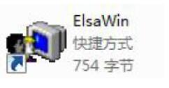
Run the shortcut on the desktop

How to Use ElsaWin 6.0 Repair & Service Software (1)

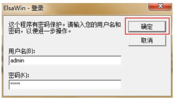
Input the username and password “admin”

How to Use ElsaWin 6.0 Repair & Service Software (2)

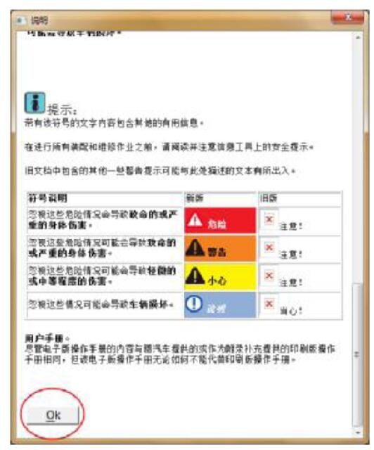
Then it will show you the massage as below,click “OK” to continue

How to Use ElsaWin 6.0 Repair & Service Software (3)

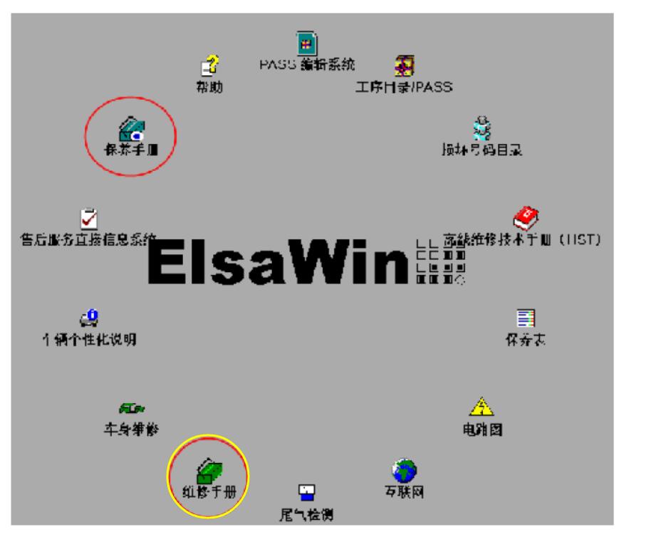
Now you have access to the menu,take “Workshop Repair Guide” as example

How to Use ElsaWin 6.0 Repair & Service Software (4)

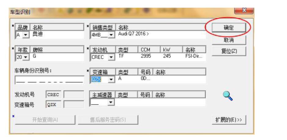
Here take Audi Q7 2016 as example,select vehicle information as below

Brand:Audi Q7 2016

Engine:CREC

Transmission:QZX

Then click “OK” to continue

How to Use ElsaWin 6.0 Repair & Service Software (5)

Now you can access the detail system & parts options,click to check as below

How to Use ElsaWin 6.0 Repair & Service Software (6)


Posted on

How to Install & Active DPF EGR LAMDA Remover 2017

How to Install & Active DPF EGR LAMDA Remover (18)

Here is a instruction for autoepccatalog.com users to install and active their DPF EGR LAMDA Remover 2017 software.After you payment,please follow this instruction to install and active it.


If you have not got it yet,please buy it here:

DPF EGR LAMDA Remover 2017


DPF EGR LAMDA Remover 2017 Installation:

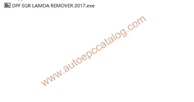
After you downloading it,please extract it,then you will get this file

How to Install & Active DPF EGR LAMDA Remover (1)

Now you need to extract it again

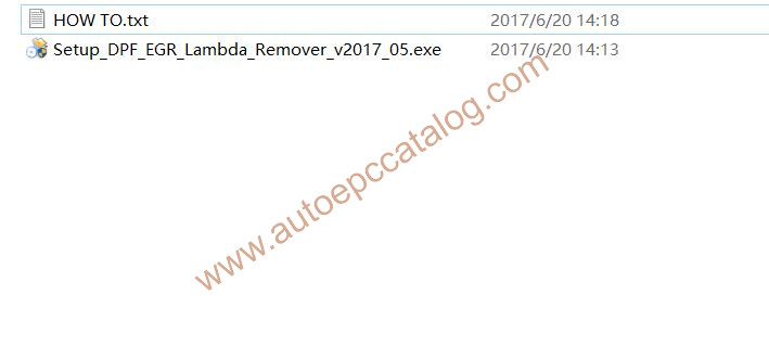
After second time extract operation,you will get below files

How to Install & Active DPF EGR LAMDA Remover (2)

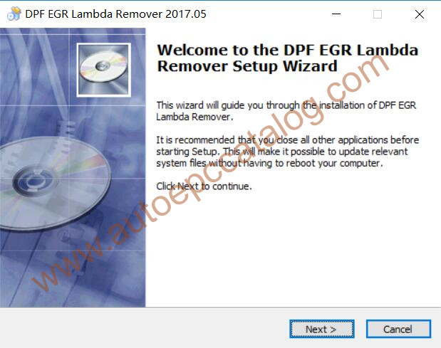
Run it to start installation,click “Next”

How to Install & Active DPF EGR LAMDA Remover (3)

Installation include,click “Next” to continue

How to Install & Active DPF EGR LAMDA Remover (10)

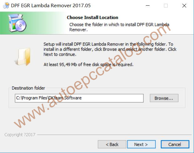
Now you need to select “Destination folder” to install

How to Install & Active DPF EGR LAMDA Remover (5)

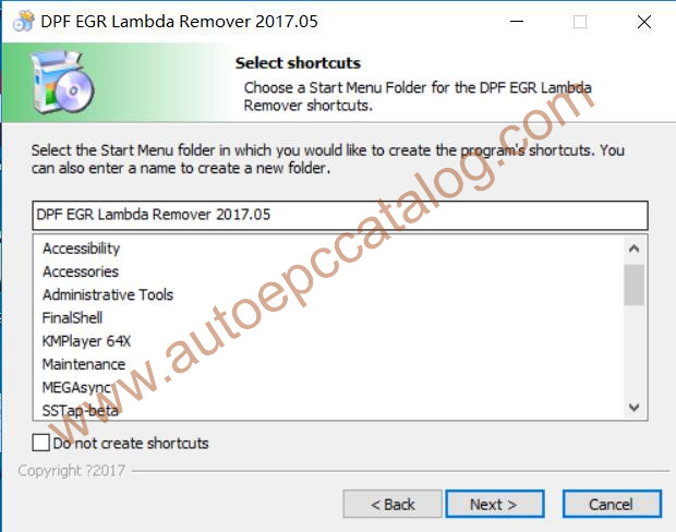
Click “Next” button to continue

How to Install & Active DPF EGR LAMDA Remover (6)

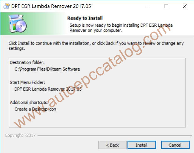
Click “Install” button to start installing

How to Install & Active DPF EGR LAMDA Remover (7)

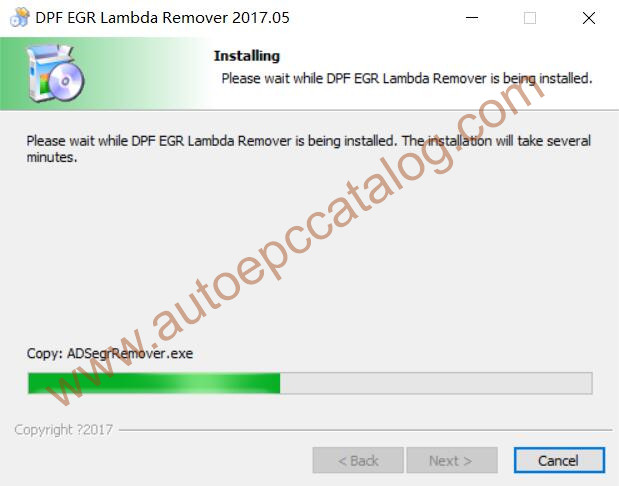
Wait for installation proceed

How to Install & Active DPF EGR LAMDA Remover (8)

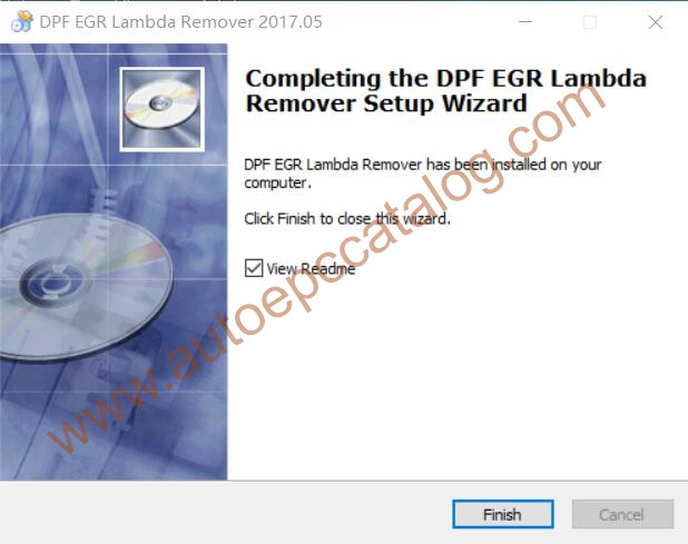
DPF EGR LAMBDA installation complete

How to Install & Active DPF EGR LAMDA Remover (9)


DPF EGR LAMBDA Activation Guide:

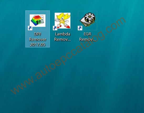
Now run one of the DPF,EGR or Lambda icon

How to Install & Active DPF EGR LAMDA Remover (10)

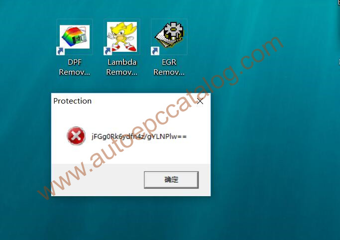
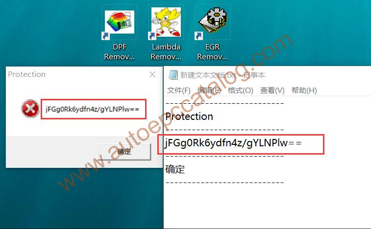
It will show you a protection error massage

How to Install & Active DPF EGR LAMDA Remover (11)

Press “Ctrl+C” to copy the Hardware ID,then create a new txt file and “Ctrl+V” to paste your HW-ID on txt file

Here the Hardware ID is “jFGg0Rk6ydfn4z/gYLNPlw==

How to Install & Active DPF EGR LAMDA Remover (12)

Now please sent this hardware id to our official email:autoepccatalog@outlook.com

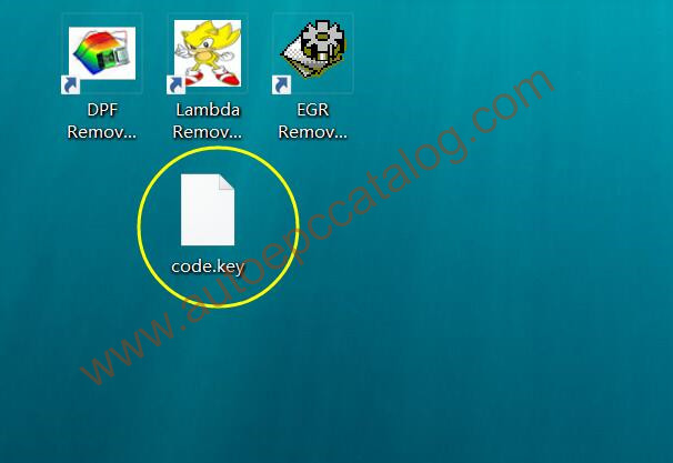
And then our online service will sent you a “code.key” file to you

How to Install & Active DPF EGR LAMDA Remover (13)

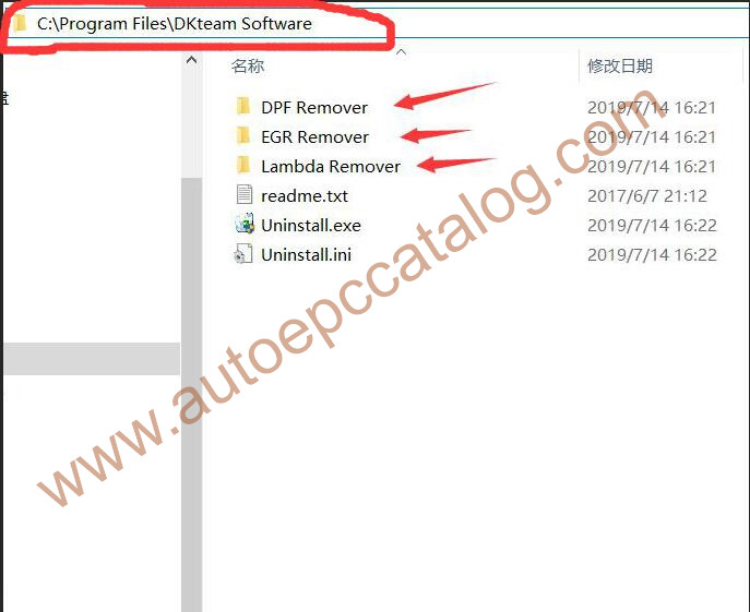
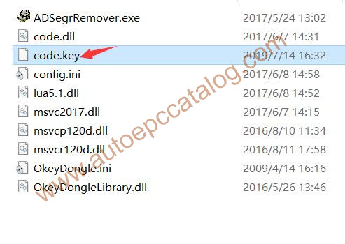
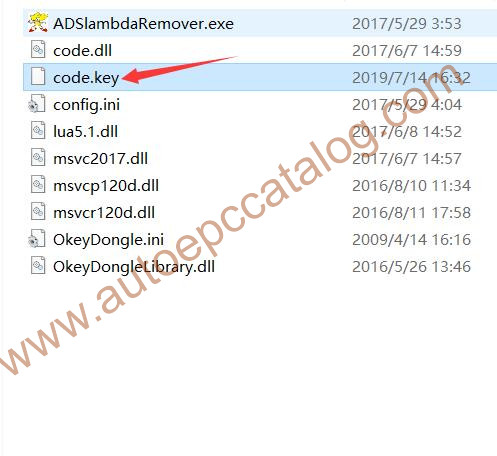
Now locate the DPF,EGR,Lambda remover installation folder

How to Install & Active DPF EGR LAMDA Remover (14)

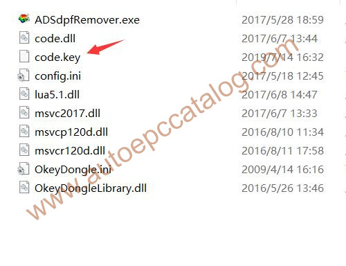
You need to copy code.key in all folders DPF/EGR/Lambda folders, for all 3 programs

C:\Program Files\DKteam Software\DPF Remover

C:\Program Files\DKteam Software\EGR Remover

C:\Program Files\DKteam Software\Lambda Remover

How to Install & Active DPF EGR LAMDA Remover (15) How to Install & Active DPF EGR LAMDA Remover (16) How to Install & Active DPF EGR LAMDA Remover (17)


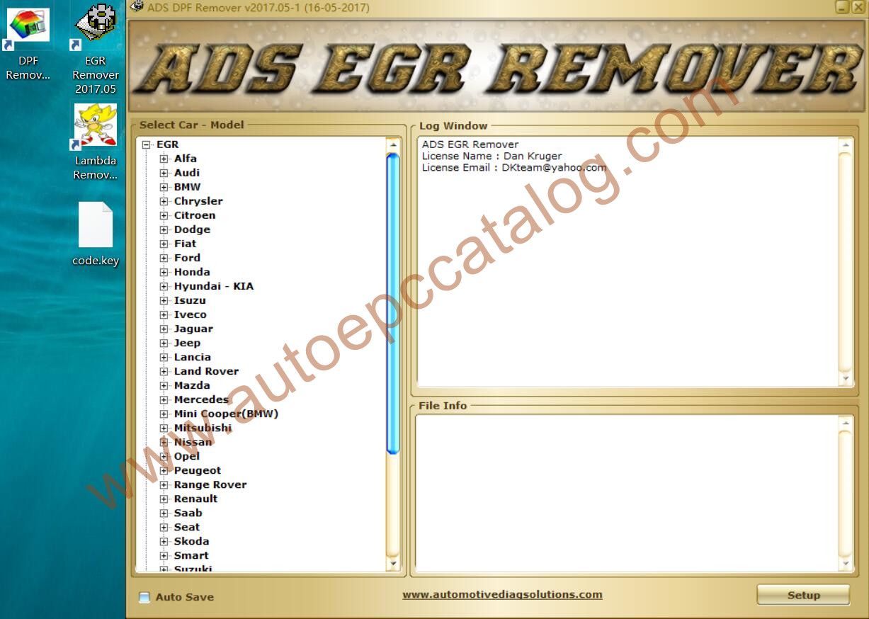
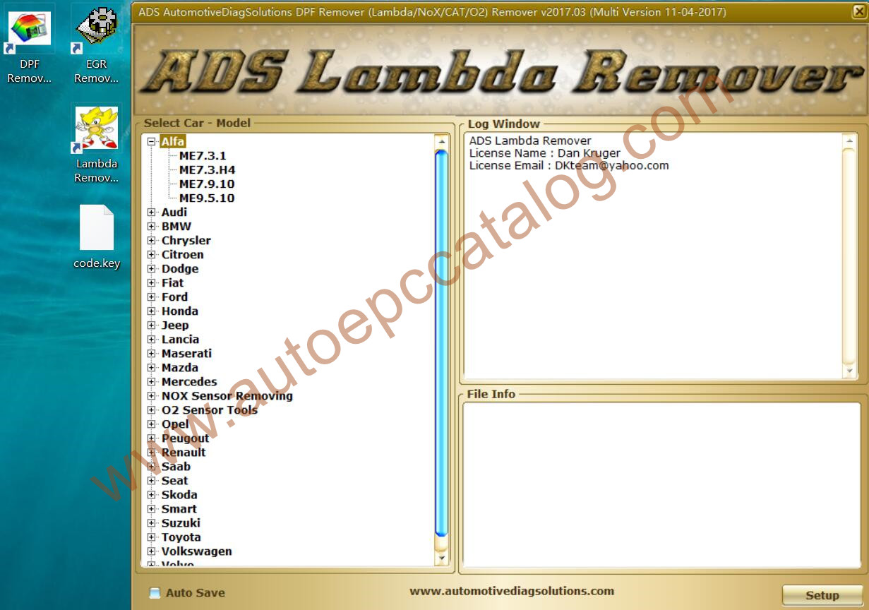
Now you run the DPF,EGR,Lambda remover software again,it can run normally

Active successfully!!!

How to Install & Active DPF EGR LAMDA Remover (18) How to Install & Active DPF EGR LAMDA Remover (19) How to Install & Active DPF EGR LAMDA Remover (20)