The engine mounted Motor Control Module (MCM) includes control logic to provide overall engine management. more Detroit Diesel you need install 2022 Detroit Diesel Diagnostic Link DDDL 8.15 10 Level+12.2021 Troubleshooting
The following is a summary of the tasks the MCM monitors:
Exhaust gas recirculation (EGR)
Intake air preheating system
Turbocharger
Diesel Particulate Filter (DPF) (EPA07 ONLY – for EPA10 the Aftertreatment Control Module (ACM) monitors the DPF)
Instrument cluster
Engine brake
Amplified Pressure Common Rail System (APCRS)
Thermal management
DDEC VI/10 provides an indication of engine and vehicle malfunctions. The MCM continually monitors the DDEC VI/10 system.
Any faults that occur are stored as codes. These codes can be accessed in any of three ways:
A DiagnosticLink ® Standard for DDEC VI/10 can be used to read the codes.
A personal computer (PC) connected to the Motor Control Module (MCM) through a translator device using SAE J1939 Data Link+, are used as the communication link, to Common Powertrain Controller (CPC) and CAN link to Motor Control Module (MCM).
The Amber Warning Lamp (AWL) (check engine) or the Red Stop Lamp (RSL) is illuminated.
The AWL (check engine) (panel mounted yellow indicator light) illuminated diagnose condition as soon as convenient, lights are CPC controlled. The RSL (panel mounted red indicator light) and AWL (check engine) illuminated, a major fault occurred and immediate attention required to avoid engine damage. Automatic engine shutdown or ramp down is available as an option. A shutdown override switch is required to allow the vehicle to be moved to a safe location during automatic shutdown or ramp down. The MCM tells the light when to activate.
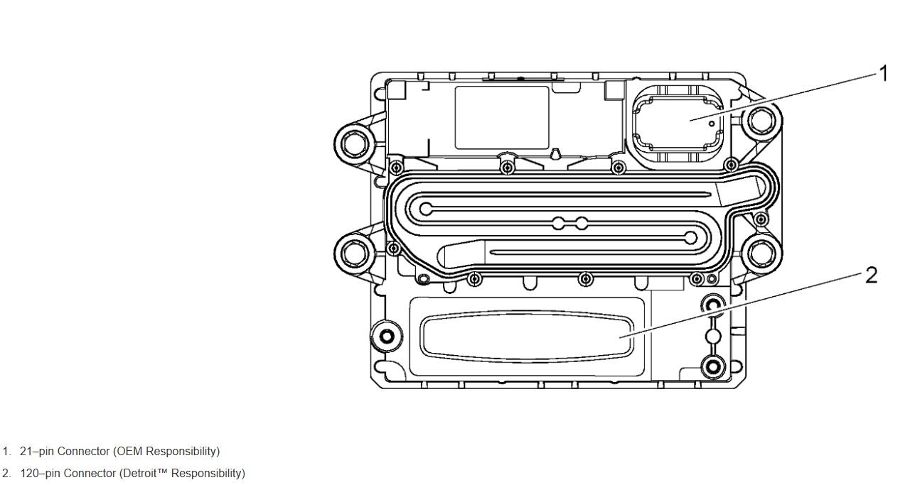
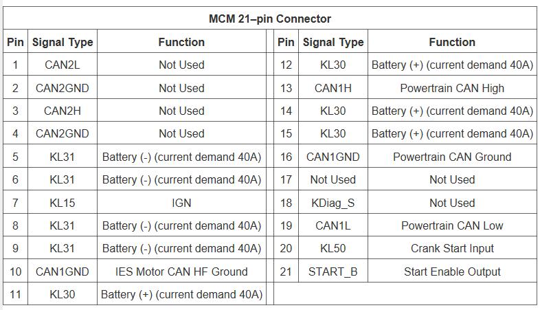
5.2.1 MCM 21–pin Connector
The wiring for the VIH 21–pin to the MCM listed in the following table. The side of the connector shown is looking into the pins.
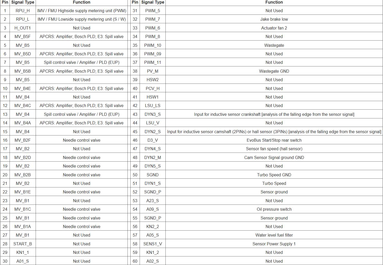
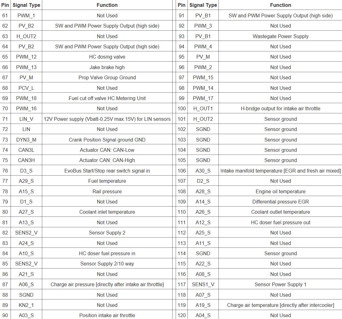
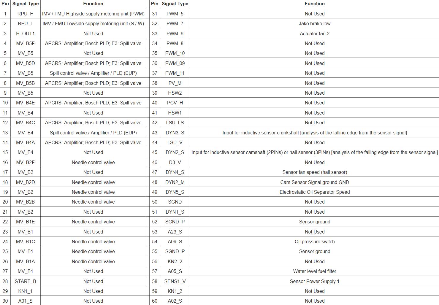
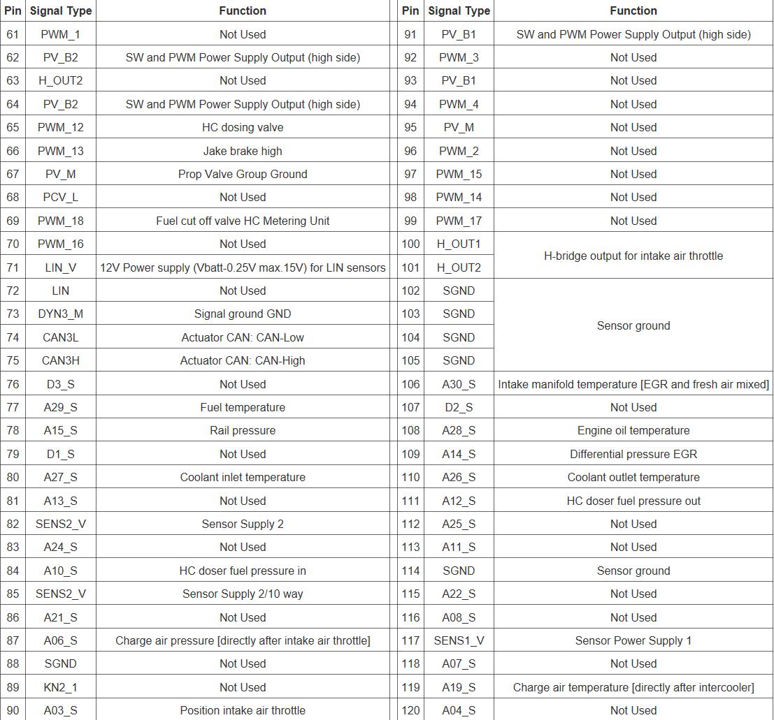
5.2.2 DD13 120-Pin Connector Pin-Out
The following tables show the 120-pin connector pin-outs for the DD13 MCM.
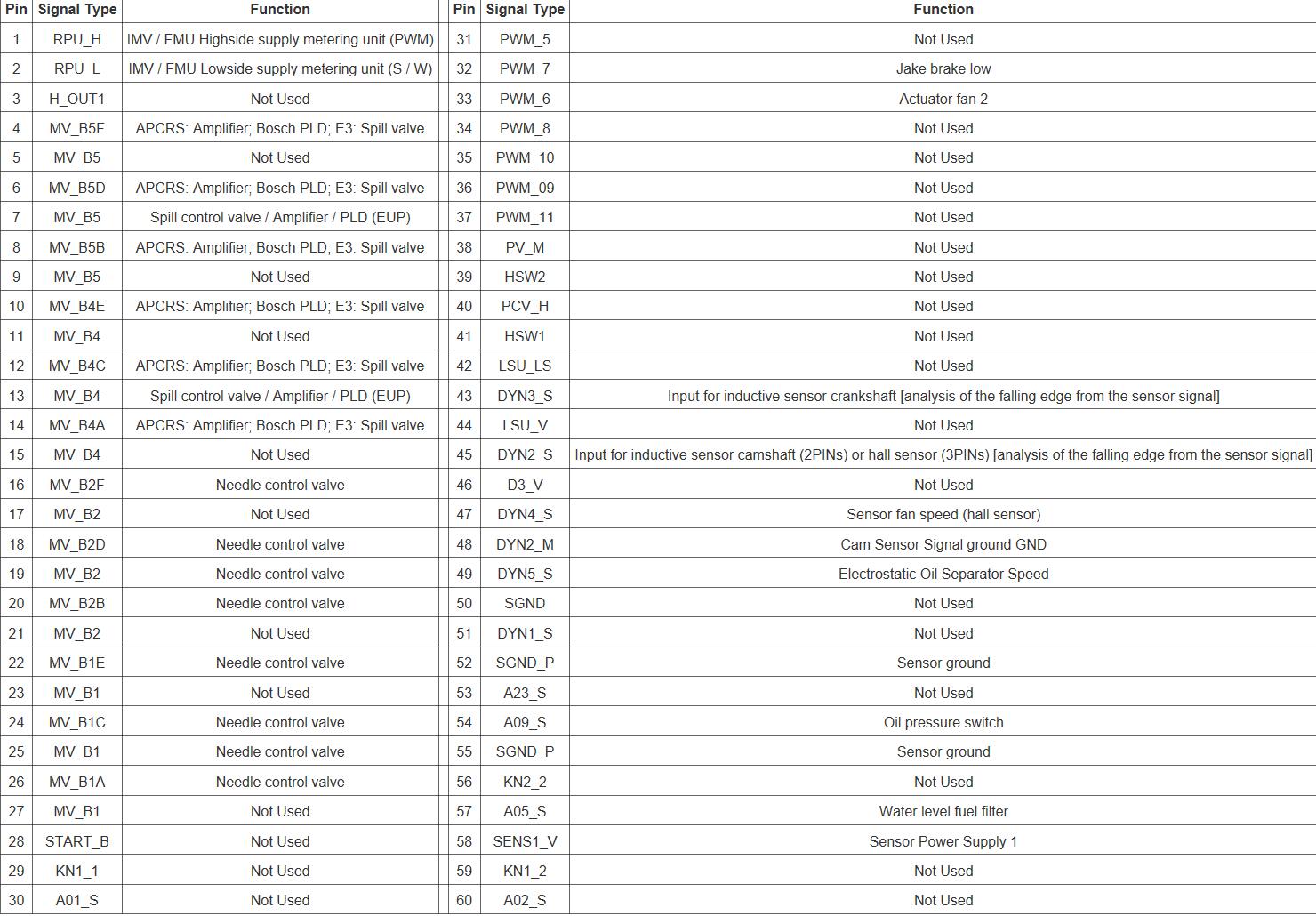
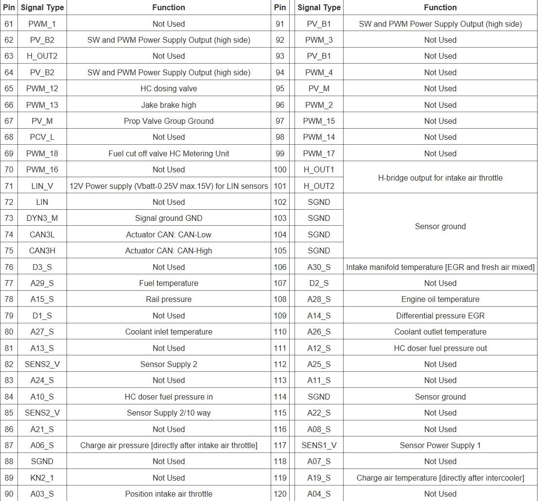
5.2.3 DD15 120-Pin Connector Pin-Out
The following tables show the 120-pin connector pin-outs for the DD15 MCM.
5.2.4 DD16 120-Pin Connector Pin-Out
The following tables show the 120-pin connector pin-outs for the DD16 MCM.
5.2.1 Removal of the Motor Control Module
Remove as follows:
1 Release latch on harness connector to remove the 21 and the 120-pin connectors from the Motor Control Module (MCM).
2 Disconnect the vehicle battery power to prevent failure of the MCM.
3 On a rear sump oil pan, disconnect the oil dipstick tube from the MCM.
4 Remove the two vehicle wiring harness retaining bolts.
5 Remove the four bolts holding the MCM to the engine, remove the MCM from engine.
5.2.2 Inspection of the Motor Control Module
Inspect the MCM-MCM2 as follows:
1 Inspect the MCM-MCM2 for damage and replace if required.
2 Inspect the ISO mounts for damage and replace if required.
5.2.3 Installation of the Motor Control Module
Install as follows:
NOTICE
Ensure the MCM metal housing does not come in contact with the chassis.
NOTICE
Ensure MCM is not contaminated with diesel fuel.
Note : If installing a new MCM; after installation, program to proper settings using the programming station.
Note : Do not ground the MCM housing. This can result in false codes being logged.
1 Confirm that vehicle battery power is disconnected and the ignition is in the OFF position.
2 Install the MCM to the engine with four bolts and isolators. Torque the MCM-to-engine bolts to 15 N·m (11 lb·ft).
3 Connect the 21 and 120-pin engine harness connectors to the MCM close and lock latch on the connectors.
4 If equipped with an MCM fuel cooler, install bracket onto fuel line; install bracket and line to MCM with two bolts.
5 If equipped with an MCM fuel cooler install both fuel lines from the MCM to the fuel filter module. Torque bolts to 55 N·m (41 lb·ft).
6 Reconnect vehicle battery power.
7 Turn the ignition to the “ON” position. Observe DiagnosticLink ® Standard for any diagnostic code(s). If any code(s) are logged, refer to the proper code diagnostics.

