Posted on

How to Solve Bobcat Stage V Engine P00AC Intake Sensor Low Fault

How to Solve Bobcat Stage V Engine P00AC Intake Sensor Low Fault (3)

Here is the instruction show you guide on how to solve Bobcat G2 Stage V engine P00AC intake manifold temperature sensor low fault.


What you need?

Doosan uVIM Diagnostic Kit

Bobcat V2 Engine Analyzer

Bobcat Diagnostic Kit


Fault Code:

P00AC:Intake manifold temperature sensor Low fault


Overview:

“E” SPNFMI:E00010504

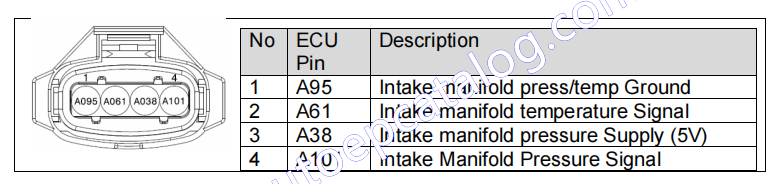
Reason:1. Electrical problem (Intake manifold temperature sensor connector)

2 Electrical problem (Wiring harness Intake manifold temperature sensor to ECU, Faulty Intake manifold temperature sensor)

3 Electrical problem (Faulty ECU, ECU connector)


Effect:CE lamp ON Inducement Group1 (EGR Block) – with EGR only DPF regeneration inhibit by Active and Forced

How to Solve Bobcat Stage V Engine P00AC Intake Sensor Low Fault (1)


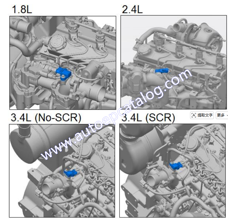
Component Location:

How to Solve Bobcat Stage V Engine P00AC Intake Sensor Low Fault (2) How to Solve Bobcat Stage V Engine P00AC Intake Sensor Low Fault (3)


Condition for Running Diagnostic

Key on or Engine running or Key off(ECU on)


Condition for Setting the Fault Code

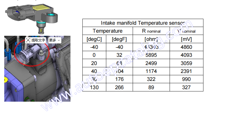
Intake manifold temperature signal is less than minimum threshold (0.151V)


Condition for Clearing the Fault Code

Intake manifold temperature signal is in operation range.


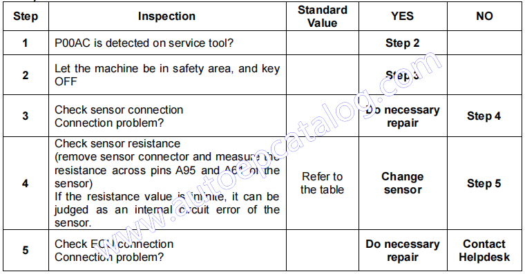
Check List

How to Solve Bobcat Stage V Engine P00AC Intake Sensor Low Fault (4)

Posted on

How to Measure and Test Fuel Return System for Fendt 900 Vario

How to Measure and Test Fuel Return System for Fendt 900 Vario (2)

Here is the instruction show you guide on how to measure and test fuel return system for Fendt 900 Vario with Deutz engine.


What your need?

AGCO 2×4 CANUSB Diagnostic Tool

Fendt Fendias 2024v2

Deutz HSlight II Diagnostic Kit

2026 AGCO EDT Diagnostic Software


If the pressure in the return line is too high, the pressure in the dispensing unit also rises. This causes too much fuel to be delivered to the high pressure pumps, which means that the pressure in the rail is above the value set by the engine control unit (A051).


Therefore, if this error occurs, the return pressure must be measured and the target and actual rail pressures must be compared using SERDIA at the same time.

How to Measure and Test Fuel Return System for Fendt 900 Vario (1)

Remove the banjo bolt from the return pipe, screw in banjo bolt with measuring connection 199.110.620.010 and connect a pressure gauge (-1 bar to +1.5 bar)

Target pressure: 0.2-0.5 bar


How to Measure and Test Fuel Return System for Fendt 900 Vario (2)

Connect SERDIA adapter (level 3) to X810 diagnostics socket and launch the program

How to Measure and Test Fuel Return System for Fendt 900 Vario (3) How to Measure and Test Fuel Return System for Fendt 900 Vario (4)


In the list, find the two values for rail pressure target value and max. rail pressure (see arrows), and compare these two values.If the return pressure is greater than 0.5 bar and the max. rail pressure is greater than the rail pressure target value, the fuel return system must be checked.


First check whether the return lines are kinked. If nothing is observed there, the components must be removed from the return system one after the other. First disconnect the return line from the engine control unit (A051) and connect it directly to the tank, then repeat the measurement. If the pressure is correct now, the problem lies in the cooler duct of the engine control unit. If the pressure is still incorrect, proceed as described above with the next component.

Posted on

How to Perform Case IH 20 Series Axial-Flow Combine Low Pressure Standby

CASE IH 20

This instruction show guide on how to perform CASE IH 20 series Axial-Flow combine low pressure standby.This test is used to determine low-pressure standby.There are two items responsible for low pressure standby,the 375-400 PSI (26-28 bar)spring on the flow compensator spool and the 0.078 mm (0 .031 in)orifice in the steering hand pump –which creates back pressure in the signal line of approximately 50-150 psi.The 375-400 PSI (26-28 bar)spring plus the back pressure will equal low-pressure standby.The following test will show the spring setting of the flow compensator spool.

CASE IH 20

Related Contents:

CNH DPA5 Diagnostic Kit

2026 CNH EST 9.14 Diagnostic Software

2026 CASE eTimGo Repair Manuals


TEST PROCEDURE

1 Attach a 69 bar (1000 psi)gauge to the signal line pressure test port (14)on the main valve assembly.It is recommended to install a needle valve in the test hose to prevent damage to the gauge.With the needle valve closed,start the engine.At low idle,open the needle valve on the gauge.Make sure that the steering wheel is not moved or that other hydraulic functions are not activated otherwise the gauge could be damaged. The signal line pressure should be approximately 50-150 PSI (3 .45-10.4 bar).Record this number for use later.


2 Then attach the SAME 69 bar (1000 psi)gauge to the PFC pump pressure test port (13) on the main valve assembly.With the needle valve closed,start the engine.At low idle open the needle valve on the gauge.Make sure that the steering wheel is not moved or that other hydraulic functions are not activated otherwise the gauge could be damaged.The PFC pump pressure port should read 375-400 PSI (26-28 bar)above the reading that was recorded from the signal line.

If the PFC pump pressure port does not read 375-400 PSI (26-28 bar)ABOVE the signal line, adjustment of the flow compensator spool spring is required.The adjustment procedure is as follows:


Example Signal line pressure port reading 112 psi (7 .7 bar) Flow compensator spool spring setting +400±25 psi (27 .5 bar

PFC pump pressure port reading AFTER adjustment 512±25 psi (35 .3 bar)


3 Remove the cap for the adjustment screw located on the compensator.

4 Loosen the jam nut.

5 Use an allen wrench to adjust the pressure to match the number calculated.(See example.)

6 Tighten the jam nut.Repeat test to verify the low-pressure standby setting.

7 If not correct,make adjustment again.If it is correct,replace the cap.

Posted on

How to Solve Liebherr Machine P1160 NH3 Sensor Heater Performance Error

Liebherr Machine P1160 NH3 Sensor Heater Performance Error (6)

This instruction show you guide on how to solve Liebherr machine trouble code P1160 NH3 sensor heater performance error.


Related Contents:

Liebherr LIDIA 2026 Diagnostic Software

Liebherr Diagnostic Kit


Compatible Machine ECU:

ECU2

D966 A7-04, D966 A7-05

D9512 A7-04


Troubleshooting:

Check the sensor

Liebherr Machine P1160 NH3 Sensor Heater Performance Error (1)

Information for engines with serial number UP TO 2018 xx xxxx (12/31/2018):
In the event of failures of NH3 sensors (ID no. 10144038) on the exhaust treatment system of Stage IV engines, the NH3 control unit (ID no. 10144039) must also be replaced ONCE to improve the service life of the NH3 sensor.
The sensor will come with an extended heat shrink tubing for improved protection of the trim resistance
This spare parts information applies for engines with a serial number up to 2018 xx xxxx (12/31/2018) : all engines with a year of manufacture starting from 2019 are already equipped with the latest version.
• In the event of a sensor failure, the sensor control unit must be replaced ONCE with a new sensor control unit.
• No active conversion is carried out. Replacement only in the event of failure.
• A repair kit with the ID 13489562 is available, it includes the sensor and sensor control unit.

Liebherr Machine P1160 NH3 Sensor Heater Performance Error (2)


Component Location

EATS All versions:

D956-D966 A7-04 (SCR only)

Liebherr Machine P1160 NH3 Sensor Heater Performance Error (3)


D956-D966 A7-05 StageV (SCR Filter)

Liebherr Machine P1160 NH3 Sensor Heater Performance Error (4) Liebherr Machine P1160 NH3 Sensor Heater Performance Error (5)


D9512 A7 04-05-StageV

Liebherr Machine P1160 NH3 Sensor Heater Performance Error (6)

Primary (A700)

Liebherr Machine P1160 NH3 Sensor Heater Performance Error (7)

Secondary (A760)

Liebherr Machine P1160 NH3 Sensor Heater Performance Error (8) Liebherr Machine P1160 NH3 Sensor Heater Performance Error (9)


Posted on

How to Solve JCB JS140 C101F-12 Fuel Level Sensor Short Circuit to Battery

How to Solve JCB JS140 C101F-12 Fuel Level Sensor Short Circuit to Battery

Here is the instruction show you guide on how to solve JCB JS140 machine trouble codes C101F-12 fuel level sensor short circuit to battery (For JS140 Side Mounted FLS).


Related Contents:
2026 JCB ServiceMaster 4

2017 JCB Parts Plus+ and Repair Service Manual

JCB Diagnostic Kit


Possible Cause:

1 Faulty fuel sensor.

2 Faulty Wire harness.

3 Faulty Display ECU.


Diagnosis:

1 Check the resistance output of fuel sensor between machine grounds & Pin no “B” of fuel sensor. Fuel sensor output shall be between 12Ω – 100Ω Refer below photograph for fuel sensor connection.

How to Solve JCB JS140 C101F-12 Fuel Level Sensor Short Circuit to Battery

2 Check the voltage on wire no. 8028 after disconnecting DECU & Fuel sensor. 24 V shall not be measured on wire no. 8028.If 24V measured on wire no. 8028 then wire got short circuited to machine supply voltage.

Follow the electrical circuit 336/F3635 for fuel sensor connection.


Corrective Action:

1 Replace the fuel sensor.

2 Replace the Faulty wire harness.

3 Replace the faulty display ECU.

Posted on

How to Solve Bobcat machine P18B0 DEF Line Heater SCB Error

How to Solve Bobcat machine P18B0 DEF Line Heater SCB Error (1)

This instruction show you guide on how to solve Bobcat machine trouble code P18B0 DEF line heater SCB error.


Related Contents:

Service Analyzer 91.15 for Bobcat Diagnostic Software

2023 Bobcat Engine Analyzer ECU DCU Diagnostic Software

Bobcat Diagnostic Tool


Code:U004340-03

Reason:

1 Electric problem (DEF line heater connector)

2 Electric problem (Heater relay, Wiring harness related DEF line heater)

3 Electric problem (DCU connector, DCU)

Effect:Inducement Group2

How to Solve Bobcat machine P18B0 DEF Line Heater SCB Error (1)


Component Location

How to Solve Bobcat machine P18B0 DEF Line Heater SCB Error (2)


3) Condition for Running Diagnostic

Power-stage is not actuated

4) Condition for Setting the Fault Code


The power-stage hardware reports a “SCB” error

➢ State of Diagnosis load feedback for Circuit 3(Pressure line) is TRUE or

➢ State of Diagnosis load feedback for Circuit 4(Backflow line) is TRUE or

➢ State of Diagnosis load feedback for Circuit 5(Suction line) is TRUE

5) Condition for Clearing the Fault Code


When no error is detected

➢ State of Diagnosis load feedback for Circuit 3(Pressure line) is FALSE or

➢ State of Diagnosis load feedback for Circuit 4(Backflow line) is FALSE or

➢ State of Diagnosis load feedback for Circuit 5(Suction line) is FALSE


6) Check List

How to Solve Bobcat machine P18B0 DEF Line Heater SCB Error (3)

Posted on

Liebherr ECU2 ECU2-HD ECU3 P1120 SCR System Out of Service Error Solution

Liebherr ECU2 ECU2-HD ECU3 P1120 SCR System Out of Service (8)

This instruction show you guide on how to solve Liebherr machine engine D966 D9512 ECU2 ECU2-HD ECU3 trouble code P1120 scr system (air pump/air supply valve) out of service.


Related Contents:

Liebherr LIDIA 2026 Diagnostic Software

Liebherr Diagnostic Kit


Reason:

The failure code is displayed during check phase :

  • Air supply is always ON (No air supply stop in Sensor Check phase)
  • Air supply is always OFF (No air supply in PreCheck 1/2/3 phase)

Liebherr ECU2 ECU2-HD ECU3 P1120 SCR System Out of Service (1)


Troubleshooting

Liebherr ECU2 ECU2-HD ECU3 P1120 SCR System Out of Service (2) Liebherr ECU2 ECU2-HD ECU3 P1120 SCR System Out of Service (3)


Consequence:

  • As the P1120-00 failure is emission relevant, the inducement process starting with P1187-00 “Inducement system – Warning (SCR failure) will begin, leading to a power reduction if the failure is not solved.
  • If a second occurrence of the failure comes back, this leads to a repeated offense issue which means that the engine will stay blocked in the latest stage of inducement. As a consequence, Service Technician is needed to remove the power reduction.


Liebherr ECU2 ECU2-HD ECU3 P1120 SCR System Out of Service (4)


Component Location:

EATS All versions

D956-D966 A7-04 (SCR only)

Liebherr ECU2 ECU2-HD ECU3 P1120 SCR System Out of Service (5)


D956-D966 A7-05 StageV (SCR Filter)

Liebherr ECU2 ECU2-HD ECU3 P1120 SCR System Out of Service (6) Liebherr ECU2 ECU2-HD ECU3 P1120 SCR System Out of Service (7)


D9512 A7 04-05-StageV

Liebherr ECU2 ECU2-HD ECU3 P1120 SCR System Out of Service (8)

Primary (A700)

Liebherr ECU2 ECU2-HD ECU3 P1120 SCR System Out of Service (9)

Secondary (A760)

Liebherr ECU2 ECU2-HD ECU3 P1120 SCR System Out of Service (10) Liebherr ECU2 ECU2-HD ECU3 P1120 SCR System Out of Service (11)


Posted on

MANITOU MT6034 Engine Oil Filter Replacement Guide

MANITOU MT6034 Engine Oil Filter Replacement Guide

Here is the instruction show you guide on how to replace engine oil filter for MANITOU MT6034.


Related Contents:

2026 Manitou I.V Interactive View Diagnostic Kit Software


Procedures:

Change the engine oil and filter using the following procedure:

1 With the engine warm, remove the crankcase drain plug located on the left side of the engine oil pan.

IMPORTANT: DO NOT discharge oil onto ground.

Catch and dispose of per local waste disposal regulations.

MANITOU MT6034 Engine Oil Filter Replacement Guide

2 The engine oil filter should be changed at every oil change interval. Using a suitable filter wrench, remove and discard the filter.

IMPORTANT: Filtration of oils is critical to proper lubrication. Always change filter with every oil

change. Use only genuine OEM engine replacement filters.

3 Apply a thin coat of clean engine oil to the sealing gasket of the new oil filter.

4 Wipe the filter sealing surface on the engine with a clean cloth.

5 Turn new oil filter on by hand until filter contacts the sealing surface then turn the filter an additional 3/4 turn.


6 Clean and re-install the drain plug.

7 Re-fill the crankcase with new oil. Follow specifications in the Lubrication chapter for type and viscosity of new oil.

NOTE: The oil capacity listed is approximate.

Always verify oil level with the engine oil dipstick.


8 After new oil has been added, run the engine at idle

speed until the oil pressure lamp is off. Check for leaks at the filter and drain plug.

9 Verfy the oil level is at the “Full” mark on the engine oil dipstick.

IMPORTANT: Low engine oil level and over full engine oil levels can cause engine damage.

Posted on

How to Solve AGCO Machine SPN 110 Coolant Temperature High Alarm

AGCO Machine

This instruction show you guide on how to solve AGCO machine trouble code SPN 110 coolant temperature high alarm.The measured coolant temperature exceeds the overheating alarm limit.

AGCO Machine

Related Contents:

AGCO 2×4 CANUSB Interface Diagnostics

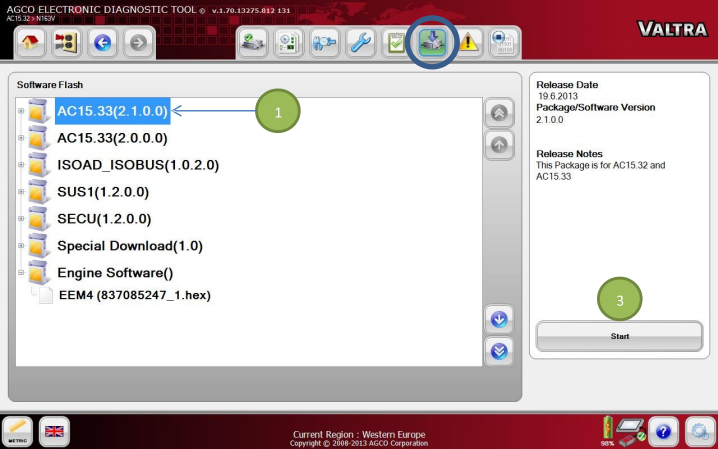
2026 AGCO EDT Electronic Diagnostic Tool


Failure Mode Indicator

FMI 00 – Above normal operational range – most severe.


Failure Mode

Fault code is stored and warning lamp is activated. The engine will stop after 30 seconds. CAN message indicates, that shutdown is pending.


Possible Cause

  • The fan belt is slipping or the belt is broken
  • Cooling system is not completely filled
  • Water pump is defective
  • Cooling system is clogged
  • Thermostat is defective or removed (double acting thermostat)
  • Thermostat is upside down.
  • Radiator filler cap is not pressure tight
  • Engine is overloaded
  • Coolant temperature sensor wiring is defective
  • Coolant temperature sensor is defective
  • Control unit is defective


Diagnosis and Solution

Find cause for the overheating indication:

  • Check the fan belt and the belt tension.
  • Check the coolant level.
  • Check condition of the radiator.
  • Check the mechanical condition of the engine.
  • Check the coolant temperature sensor wiring, connectors and contact surfaces of the connector pins (possible oxidation).


Coolant Temperature Sensor

Check the coolant temperature sensor operation.

Coolant Temperature Sensor

Check the ECU operation with another EEM3 controller. If the system is functional and the fault is not active with the replacement ECU, then the original ECU is defective.

ECU Replacement


Posted on

JCB JCB 3CX 4CX Backhoe Loader Load Sensing Flow and Pressure Testing

This instruction show you guide on how to perform load sensing flow and pressure test for JCB JCB 3CX 4CX Backhoe loader.

Related Contents:
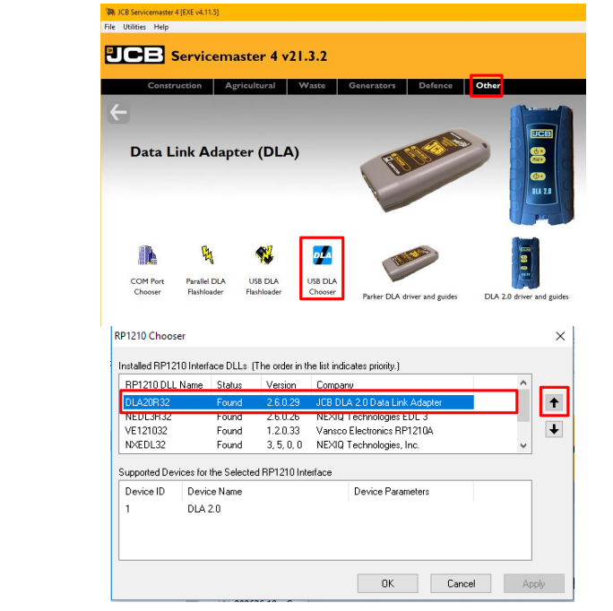
2025 JCB ServiceMaster 4 v25.1.0 Free Download for Win 10 Win11

2017 JCB Parts Plus+ and Repair Service Manual Free Download

JCB Diagnostic 72826500 Kit


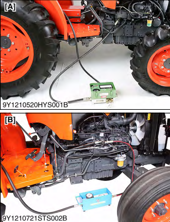
With no services operating, there should be no pressure in the load sense line, this is because hydraulic oil flows through the load sense circuit back to the hydraulic tank. If a shuttle valve is ‘stuck’, or a hose kinked, then a pressure could be induced in the load sense lines, this will have an effect on the hydraulic system. To check load sense pressure:

1 Warm the hydraulic oil to working temperature, i.e. 50°C (122°F):

a Set the engine speed to 2200 rev/min.

b Operate the loader shovel dump service to blow off the auxiliary relief valve.


2 Lower the backhoe bucket and loader shovel to rest on the ground; stop the engine; operate the control levers to vent residual hydraulic pressure.

3 Connect a 0 – 400 bar (0 – 6000 lbf/in2) pressure gauge to pressure test connector A located on the load sense line from the loader valve.

4 Start the engine and run at 2200 rev/min.

5 Do not move the steering wheel and make sure that all control levers remain in ‘neutral’ position.

6 Check the pressure gauge reading, which should be as specified in Technical Data.

7 If the pressure is higher than specified, first move the steering wheel and then any of the service levers. If this does not reduce the pressure, physically check the load sense lines for trapping or kinking. As a last resort, the service valves may have to be removed and checked for sticking shuttle valves. However, this should not be done until all other checks have been completed.

8 Machines with the load sense pressure relief valve adjust the load sense pressure relief valve E. Machines without a load sense pressure relief valve adjust the regulator valve.