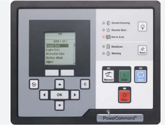
Here is a how to guide on PowerCommand PCC2300 fault code 144 engine coolant temperature OOR high.Engine coolant temperature signal voltage is out of range – shorted high.
Related Contents:
2025 InPower V16 Pro V12 Diagnostic Software Free Download
PowerCommand Diagnostic 9 Pin Adapter Cable for InPower
Possible Causes:
1 Fault simulation feature is enabled.
2 Faulty coolant temperature sensor connections.
3 Faulty coolant temperature sensor.
4 Faulty engine harness.
5 Faulty extension harness.
Diagnosis and Repair:
1 Verify that the fault simulation feature is not enabled
Connect InPower.
Verify that the fault simulation is NOT enabled for the intake manifold temperature sensor by
connecting to the PCC via InPower. If fault simulation is disabled, there is no problem.
2 Coolant temperature sensor connections
Inspect the coolant temperature sensor and the harness connector pins.
Disconnect the engine harness connector from the coolant temperature sensor.
Inspect for corroded pins, bent pins, broken pins, pushed-back pins or expanded pins.
Inspect for evidence of moisture in or on the connector.
Inspect for missing or damaged connector seals.
Inspect for dirt or debris in or on the connector pins.
3 Faulty sensor.
Check the resistance of the sensor.
Disconnect the engine harness connector from the coolant temperature sensor.
Measure the resistance between the coolant temperature signal pin and the coolant
temperature return pin.
Refer to the troubleshooting and repair manual for the specific engine platform for coolant
temperature ranges.
4 Faulty engine harness
Inspect the engine harness and the extension harness connector pins.
Disconnect the engine harness connector from the extension harness.
Inspect for corroded pins, bent pins, broken pins, pushed-back pins or expanded pins.
Inspect for evidence of moisture in or on the connector.
Inspect for missing or damaged connector seals.
Inspect for dirt or debris in or on the connector pins.
Check for a short circuit from pin-to-pin.
Disconnect the engine harness connector from the extension harness.
Disconnect the engine harness from the coolant temperature sensor.
Disconnect the engine harness from all sensors that have a shared return with the coolant
temperature sensor.
Measure the resistance from the coolant temperature return pin on the engine harness inline
connector to all other pins in the engine harness inline connector.
Measure the resistance from the coolant temperature signal pin on the engine harness inline
connector to all other pins in the engine harness inline connector.
If all measurements are greater than 100K ohms, then the resistance is correct.
Check for an open circuit.
Disconnect the engine harness connector from the extension harness.
Disconnect the engine harness from the coolant temperature sensor.
Measure the resistance from the coolant temperature return pin on the engine harness inline
connector to the coolant temperature return pin on the engine harness sensor connector.
Measure the resistance from the coolant temperature signal pin on the engine harness inline
connector to the coolant temperature signal pin on the engine harness sensor connector.
If the measurements are less than 10 ohms, then the resistance is correct.
5 Faulty extension harness
Inspect the extension harness and the AUX105 connector pins.
a Disconnect the engine harness connector from the AUX105.
b Inspect for corroded pins, bent pins, broken pins, pushed-back pins or expanded pins.
c Inspect for evidence of moisture in or on the connector.
d Inspect for missing or damaged connector seals.
e Inspect for dirt or debris in or on the connector pins.
Check for an open circuit.
Disconnect the extension harness from the AUX105.
Disconnect the extension harness from the engine harness.
Measure the resistance from the coolant temperature return pin on the extension harness
connector to the coolant temperature return pin on the extension harness inline connector.
Measure the resistance from the coolant temperature signal pin on the extension harness to
the coolant temperature signal pin on the extension harness inline connector.
If the measurements are less than 10 ohms, then the resistance is correct.
Check for a short circuit from pin-to-pin.
Disconnect the extension harness from the AUX105.
Disconnect the extension harness from the engine harness.
Measure the resistance from the coolant temperature return pin on the extension harness
connector to all other pins in the extension harness connector.
Measure the resistance from the coolant temperature signal pin on the extension harness
connector to all other pins in the engine harness connector.