This instruction show you guide on how to perform load sensing flow and pressure test for JCB JCB 3CX 4CX Backhoe loader.
Related Contents:
2025 JCB ServiceMaster 4 v25.1.0 Free Download for Win 10 Win11
2017 JCB Parts Plus+ and Repair Service Manual Free Download
JCB Diagnostic 72826500 Kit
With no services operating, there should be no pressure in the load sense line, this is because hydraulic oil flows through the load sense circuit back to the hydraulic tank. If a shuttle valve is ‘stuck’, or a hose kinked, then a pressure could be induced in the load sense lines, this will have an effect on the hydraulic system. To check load sense pressure:
1 Warm the hydraulic oil to working temperature, i.e. 50°C (122°F):
a Set the engine speed to 2200 rev/min.
b Operate the loader shovel dump service to blow off the auxiliary relief valve.
2 Lower the backhoe bucket and loader shovel to rest on the ground; stop the engine; operate the control levers to vent residual hydraulic pressure.
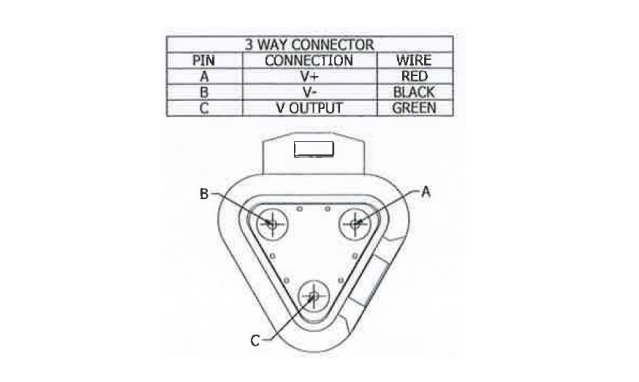
3 Connect a 0 – 400 bar (0 – 6000 lbf/in2) pressure gauge to pressure test connector A located on the load sense line from the loader valve.
4 Start the engine and run at 2200 rev/min.
5 Do not move the steering wheel and make sure that all control levers remain in ‘neutral’ position.
6 Check the pressure gauge reading, which should be as specified in Technical Data.
7 If the pressure is higher than specified, first move the steering wheel and then any of the service levers. If this does not reduce the pressure, physically check the load sense lines for trapping or kinking. As a last resort, the service valves may have to be removed and checked for sticking shuttle valves. However, this should not be done until all other checks have been completed.
8 Machines with the load sense pressure relief valve adjust the load sense pressure relief valve E. Machines without a load sense pressure relief valve adjust the regulator valve.