Posted on

Kubota L3301 L3901 L4701 Machine Hydraulic Flow Test

How to perform hydraulic flow test for Kubota L3301 L3901 L4701 tractor machine.


IMPORTANT

When using a flowmeter other than KUBOTA specified flowmeter, be sure to use the instructions with that flowmeter.

Do not close the flowmeter loading valve completely, before testing, because it has no relief valve.


What you need?

Kubota DST-i Diagnostic Adapter

2026 Kubota DiagMaster 26.01.01


Preparations:

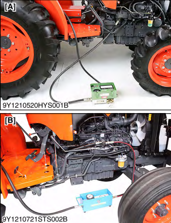
1 Remove the power steering delivery pipe or delivery hose joint bolt and install the pump adaptor 2 to the pump discharge port.

2 Connect the hydraulic test hose to the pump adaptor 2 and flowmeter inlet port.

3 Connect the other hydraulic test hose to the flowmeter outlet port and to transmission fluid filling plug hole.

4 Open the flowmeter loading valve completely. (Turn counterclockwise.)

5 Start the engine and set the engine speed at 2000 to 2200 min-1 (rpm).

6 Slowly close the loading valve to generate pressure approx.

9.81 MPa (100 kgf/cm2 , 1420 psi). Hold in this condition until oil temperature reached approx. 40 °C (104 °F).

7 Open the loading valve completely.

8 Set the engine speed. (Refer to Condition.)

9 Read and note the pump delivery at no pressure.

10 Slowly close the loading valve to increase pressure (Rated pressure). As the load is increased, engine speed drops,therefore, reset the engine speed.

11 Read and note the pump delivery at rated pressure.

12 Open the loading valve completely and stop the engine.

13 If the pump delivery does not reach the allowable limit, check the pump suction line, oil filter or hydraulic pump.
 

Posted on

Kubota L3301 L3901 Tractor Relief Valve Setting Pressure

Kubota L3301 L3901 Tractor Relief Valve Setting Pressure (1)

Here is the instruction show you guide on how to perform relief valve setting pressure for Kubota L3301 L3901.


Related Contents:

[06.2025] Kubota DiagMaster 25.02.01 Level 9 Takechi,Manitou,Carrier,Nonself

[06.2021]Kubota EPC PAD KDG+LinkOne EPC 2003 2 in 1 VMware

Genuine Kubota DST-i Diagnostic Adapter


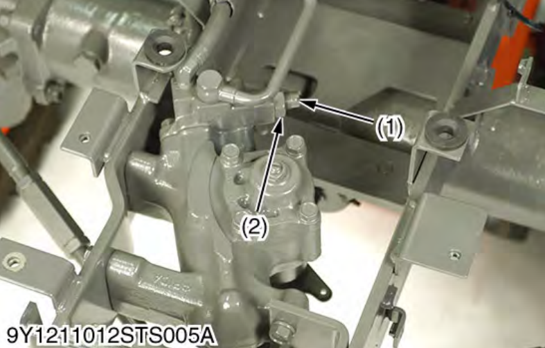
Relief Valve Setting Pressure

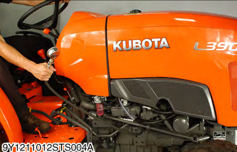
1 Disconnect the power steering delivery pipe joint bolt.

2 Install the adaptor E instead of joint bolt, and then set a thread joint, cable and pressure gauge.

3 Start the engine and set the engine speed at max. speed.

Kubota L3301 L3901 Tractor Relief Valve Setting Pressure (1)

4 Fully turn the steering wheel to the left or right and read the pressure when the relief valve functions.

5 Stop the engine.

6 If the pressure is not within the factory specifications, check the pump delivery line, and adjust relief valve setting pressure by turning adjusting screw (1).

Kubota L3301 L3901 Tractor Relief Valve Setting Pressure (2)

Posted on

Kubota L4701 Tractor Clutch Housing and Mid Case Separating

Kubota L4701 Tractor Clutch Housing and Mid Case Separating-1

Here is the instruction show you guide on how to separate clutch housing and mid for Kubota L4701 tractor.


Related Contents:

[06.2025] Kubota DiagMaster 25.02.01 Level 9 Takechi,Manitou,Carrier,Nonself

[06.2021]Kubota EPC PAD KDG+LinkOne EPC 2003 2 in 1 VMware

Genuine Kubota DST-i Diagnostic Adapter


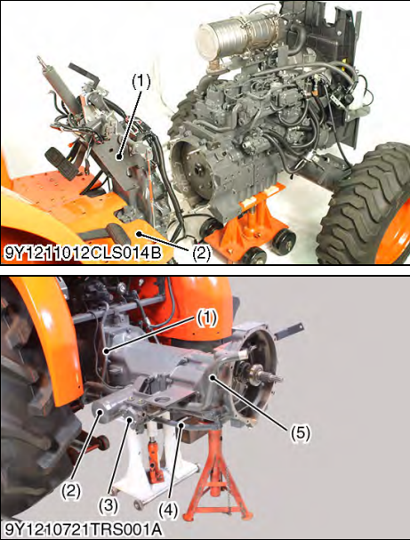
Outer Components

1 Remove the mounting bolts and the steering support (1).

2 Disconnect the differential lock pedal.

3 Remove the step (2) and the main wiring harness.


Suction Pipe and Hydraulic Block

1 Remove the suction pipe (5).

2 Remove the hydraulic block (3).

3 Remove 3P delivery pipe (1).

4 Remove the brake connecting rod R.H. (4) and L.H.. (When reassembling)

Apply grease to the O-rings.

Kubota L4701 Tractor Clutch Housing and Mid Case Separating-1


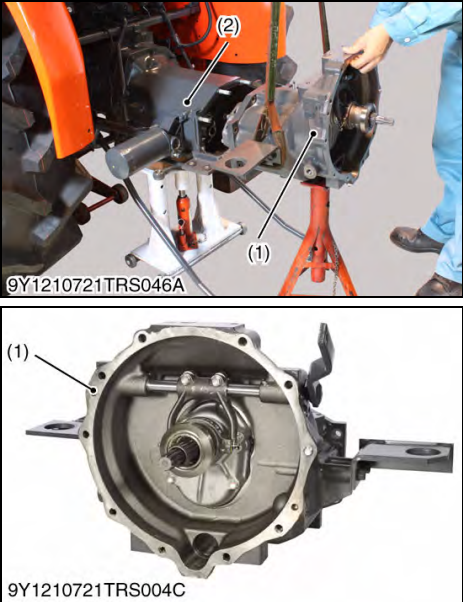
Separating Clutch Housing Case from Mid Case

1 Loosen and remove the screws and the nuts securing the clutch housing case (1) to mid case (2).

2 Separate the clutch housing case (1) from the mid case (2). (When reassembling)

Replace the gasket with a new one.

Kubota L4701 Tractor Clutch Housing and Mid Case Separating-2


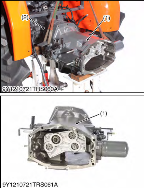
Separating Mid Case from Transmission Case

1 Loosen and remove screws and nuts securing mid case (1) to transmission case (2).

2 Separate mid case from transmission case (2).

(When reassembling)

Apply liquid gasket (Three Bond 1208D or equivalent) to joint face of mid case and transmission case after eliminate water, oil and stuck liquid gasket.

Kubota L4701 Tractor Clutch Housing and Mid Case Separating-3

Posted on

Kubota L3301 Excavator Cruise Control Linkage and Maximum Travel Speed

Kubota L3301 Excavator Cruise Control Linkage and Maximum Travel Speed (3)

Kubota L3301 Excavator Cruise Control Linkage and Maximum Travel Speed


Related Contents:

[06.2024] Kubota DiagMaster 24.06.01 Level 9 Takechi,Manitou,Carrier,Nonself

[06.2021]Kubota EPC PAD KDG+LinkOne EPC 2003 2 in 1 VMware

Genuine Kubota DST-i Diagnostic Adapter for Kubota Takeuchi Machine


CAUTION
• Stop the engine when adjusting the cruise control linkage and pedal stroke.
NOTE
• Be sure to adjust the HST neutral position.
• Be sure to check whether the “traveling speed coefficient” is suitable for tire size.
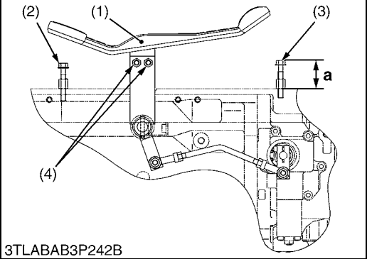
1. Loosen the HST pedal mounting screws (4) and tighten the screws (4) while pulling up the front of HST pedal (1).
2. Adjust the height a of the pedal stopper bolt (Forward) (3) to approx. 25 mm (0.98 in.) from the step.
3. Operate the tractor actually and make whether the tractor can put on sufficient speed.
4. Set the cruise control lever to fully forward (Maximum position).
HST pedal also tilts.
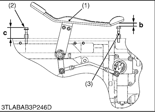
5. Measure the clearance b between bottom of HST pedal and tip of pedal stopper bolt (Forward) (3).

Kubota L3301 Excavator Cruise Control Linkage and Maximum Travel Speed (1) Kubota L3301 Excavator Cruise Control Linkage and Maximum Travel Speed (2)


6.If the measurement is not within factory specification, adjust by the cruise adjusting rod (5). (Cruise Linkage Adjustment.)

Kubota L3301 Excavator Cruise Control Linkage and Maximum Travel Speed (3)

7.Shorten the pedal stopper bolt (Reverse) (2) to the position where the length of the bolt is not touched to the HST pedal (1) even if the HST pedal is fully depressed rearward.
8. Lengthen the length of the pedal stopper bolt (Reverse) (2) gradually with the HST pedal fully depressed rearward to contact to the HST pedal.

(Reference)
• Height “a”: 25 mm (0.98 in.)
• Clearance “b”: 2 to 6 mm (0.08 to 0.2 in.)
• Height “c”: 15 mm (0.59 in.)


(1) HST Pedal
(2) Pedal Stopper Bolt (Reverse)
(3) Pedal Stopper Bolt (Forward)
(4) HST Pedal Mounting Screw
(5) Cruise Adjusting Rod
a: Stopper Bolt Height (Forward)
b: Clearance between HST pedal
and stepper bolt (Forward)
c: Stopper Bolt Height (Reverse)
F: Forward
R: Reverse