This instruction show you guide how to perform inverter radiator replacement for J05E engine.
Related Contents:
Nexiq USB Link 3
HINO DX3 2025
HINO Truck Service Manual 2022 Workshop Repair Book
Procedures:
1 Removing the PCU.
Reference: Hybrid, hybrid system, PCU, replacement,Removing the PCU
2 Removing the under cover.
Reference: Hybrid, hybrid system, hv battery,
Replacement, removing the hv battery assembly
3.Disconnecting the bottom ofPCU.
Reference: Hybrid, hybrid system,HV battery,
Replacement, removing the HV battery assembly
4 Removing the inverter radiator.
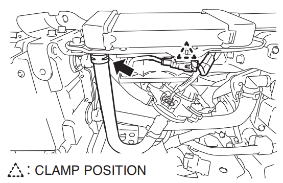
(1) disconnect the connector and connector clamp.
(2) remove the clamp to separate the hose.
! Caution
Use a tray or something similar to catch the coolant.
(3) disconnect the harness clamp.
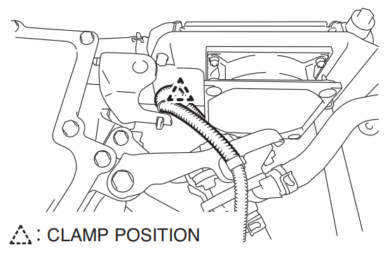
(4) remove the clamp to separate the hose.
! Caution
Use a tray or something similar to catch the coolant.
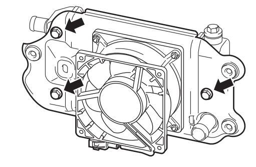
(5) remove the bolts (3 pcs.) and remove the inverter radiator Assembly.
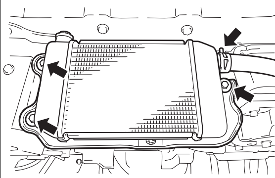
(6) unfasten the bolts (3 pcs.) to remove the fan assembly from The inverter radiator.
Mounting the inverter radiator
1 Mounting the inverter radiator
(1) mount the fan assembly to the inverter radiator with the bolts (3 pcs.).
Tightening torque:
9 n·m {92 kgf·cm, 6.6 lbf·ft}
(2) mount the inverter radiator assembly with the bolts (3 pcs.).
Tightening torque:
12.5 n·m {127 kgf·cm, 9.2 lbf·ft}
(3) connect the hoses and attach the clamps.
(4) connect the harness clamp.
(5) connect the hoses and attach the clamps.
(6) connect the connector clamp and connector.
2 Adding coolant
Reference: Hybrid, hybrid system, coolant, replace�
Ment, add coolant
3 Mounting the bottom of PCU
Reference: Hybrid, hybrid system, hv battery,
Replacement, mounting the hv battery assembly
4 Mounting the under cover.
Reference: Hybrid, hybrid system, hv battery,
Replacement, mounting the hv battery assembly
5 Mounting the PCU
Reference: Hybrid, hybrid system, pcu, replacement,
Mounting the PCU