This instruction show you guide on how to assemble turbocharger for John Deere PowerTech 9.0L OEM engine.
Related Contents:
John Deere Service Advisor EDL2
2024 John Deere Service Advisor 5.3.235
John Deere Parts ADVISOR EPC 2024
Assemble Turbocharger
IMPORTANT: If turbocharger failed because of foreign material entering the air intake system,be sure to examine the system and clean as required to prevent a repeat failure.
Visually inspect the charge air cooler and piping for residual oil and clean if necessary. Oil may have accumulated from the failed turbo.
Failure to clean residual oil from the intake system may result in engine failure.
If not previously done, prime (prelube) turbocharger rotating assembly prior to installing turbocharger on engine. Prelube center housing with clean engine oil through oil return (drain) hole.. Turn rotating assembly by hand to lubricate bearings.
NOTE: Two threaded guide studs may be used to hold turbocharger-to-exhaust manifold gasket in place and aid in turbocharger installation. Place guide pins in threaded manifold mounting holes.
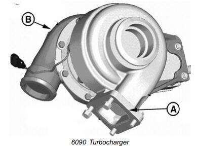
1 Install new gasket (A) over guide pins.
2 Position turbocharger on exhaust manifold over guide pins, with compressor inlet (B) facing front of engine.
3. Apply PT569 NEVER-SEEZ® Compound to all turbocharger mounting cap screws. Install 2 cap
screws through exhaust manifold into threaded holes of turbocharger finger tight.
4 Remove guide pins and install remaining 2 cap screws through turbocharger into exhaust manifold finger tight.
5 Tighten 4 cap screws to specification
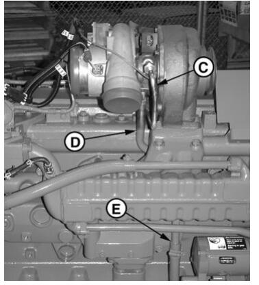
Install turbocharger oil supply line (C) to oil filter base and turbocharger. Tighten securely.
7 Install oil drain line (D) behind exhaust manifold with flange end toward turbocharger.
8 Install 2 serrated cap screws through flange.
9 Install new gasket over cap screws and install flange end of drain line to turbocharger bearing housing. tighten cap screws to specification.
Specification
Turbocharger Oil Return
Line—Torque…………………………………………………………35 N•m ˙ (25 lb-ft)
10 Apply soap lubricant to inside diameter of turbo drain hose.
11 Install drain hose over end of drain line (E). Position tension clamp over hose and line joint.
12 Connect coolant supply line (G) to turbocharger actuator and tighten securely
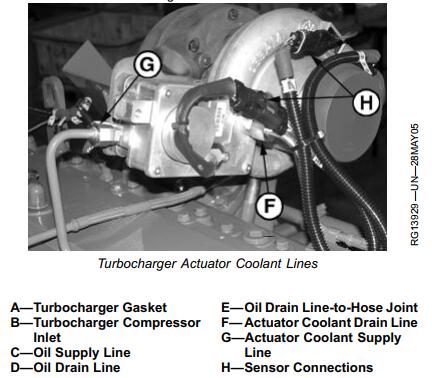
13 Connect coolant drain line to turbocharger actuator (F) and tighten securely.
14 Connect both sensors to wiring harness (H).
15 Connect air intake and exhaust piping to turbocharger.
Tighten all connections securely. (For vehicle engines,refer to machine Technical Manual.)
IMPORTANT: BEFORE STARTING an engine with a new or repaired turbocharger, crank the engine
over (but do not start) for several seconds to allow engine oil to reach turbocharger bearings.
DO NOT crank engine longer than 30 seconds at a time to avoid damaging starting motor.
16 Start and run engine at low idle while checking oil inlet and air piping connections for leaks.
NEVER-SEEZ is a registered trademark of Emhart Chemical Group