The Parked SCR Efficiency Test is supported on:
✓ Detroit Diesel EPA 10 to EPA 13 all DD13, DD15, and DD16 engines ✓ Detroit Diesel GHG17 and newer with Engine Software Version: o App_040B o App_040D o App_0411 o App_2108 o App_2104 o App_2109
and ACM Software Version:
o acm_0x0232 o acm_0x0236 o acm_0x023E o acm_0x0250 o acm_0x024E The Parked SCR Efficiency Test validates the SCR system integrity from engine warm up through NOx efficiency. It may be used for diagnosing SCR catalyst efficiency or DEF concentration concerns.
Related Contents:
JPRO Noregon Commercial Fleet Diagnostics 2024
Noregon JPRO DLA+ 2.0 Adapter
Steps:
1 Select the Parked SCR Efficiency Test and press Enter or select the Start button.
2 If not previously shown, the Aftertreatment Instructions are automatically displayed to provide aid in diagnosing issues with aftertreatment systems. When read, select the Close button on the window.
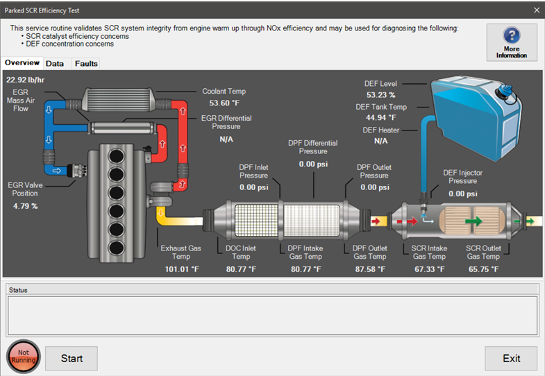
3 The Parked SCR Efficiency Test dialog will be displayed.
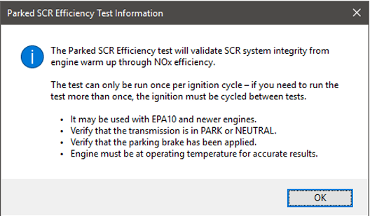
4 Select the More Information button to view additional details concerning this test.
5 Select the Data tab to view data related to the aftertreatment system as well as a graph of temperature values.
6 Select the Faults tab to view all active fault conditions for the engine and aftertreatment system.
7 To begin the test, press the Start button. The lamp to the left of the Start button will change from “Not Running” to “Running” and highlight as well. The button will change to Stop. NOTE: The transmission must be in park or neutral and the parking brake must be applied prior to starting the test.
NOTE: The engine must be at operating temperature for accurate results.
8 As the test runs, the status area will show what is occurring and the current state. Once the test completes, the status area will display the test results.
9 To end test at any time, press the Stop button. 10. To leave this dialog, select the Exit button.