This instruction show you guide on how to solve Caterpillar C9 Engine trouble code 29 30-8 PTO throttle signal invalid error.
Related Contents:
Caterpillar 18 digits factory password calculator
The Engine Control Module (ECM) detects the following conditions:
The “PTO Configuration” is programmed to “Remote Throttle”.
The ECM is not receiving a valid signal from the PTO throttle.
The ECM has been powered for at least three seconds.
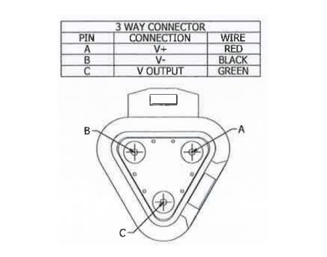
A remote accelerator position sensor may be used for PTO purposes The remote accelerator position sensor should be connected to terminal 1Pr-68 of the Engine Control Module ECM).Before the ECM will respond to the remote accelerator position sensor, the ECM”PTO Configuration” must be programmed to “Remote Throttle”, and the “PTO On/Off Switch” must be in the ON position.
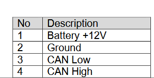
The remote accelerator position sensor must be powered from the vehicle battery(+ 12 V).A +12 V version of the accelerator position sensor must be used for the remote accelerator position sensor,and the +8 V version for the accelerator pedal position sensor must be used in the cab.
The ECM will not respond to the remote accelerator position sensor while 253-02 diagnostic-code is active.Refer to Troubleshooting,”ECM Memoy-Test if 253-02 diagnostic code is active.
The remote accelerator position sensor provides a throttle position signal to the ECM.The output of the remote accelerator position sensor is a constant frequency signal with a pulse width that varies with the position of the sensor.This output signal is referred to as either a duty cycle or a pulse width modulated signal (PWM).
The output signal of the remote accelerator position sensor is expressed as a percentage between 3 and 100 percent.The accelerator position sensor will produce a duty cycle of 10 to 22 percent at low idle and 75 to 90 percent when the sensor is fully actuated. The percent of duty cycle is translated in the ECM into a throttle position of 3 to 100 percent.
If the vehicle is using the ECM dedicated PTO functions, the accelerator position sensor will be ignored while the engine is in “PTO Mode’ and the “PTO Configuration” is programmed to the “Remote Throttle” option.
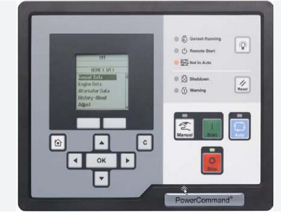
The ECM is in”PTO Mode” while the PTO on/off switch is on. This can be checked through the status screen on Caterpillar Electronic Technician (ET).
The ECM will not respond to the remote accelerator position sensor when both of the following conditions are met:
The PTO on/off circuit is switched from the OFF position to the ON position.
The ECM reads the remote accelerator position sensor above low idle.
This prevents the engine from experiencing unexpected acceleration or sudden acceleration when the PTO on/off circuit is turned on.The remote accelerator position sensor must return to low idle before the ECM will respond. The ECM must also see a transition from the OFF position to the ON position in the PIO on/off switch in order to Allow the other PIO speed control functions to operate.If the engine is started with the PTO on/off switch in the ON position, the accelerator will respond. The response will occur only if the accelerator pedal is first returned to the low idle position, The other engine speed controls will not respond.
Probable Causes:
1 ECM Connection
2 Remote accelerator position sensor
3 Remote accelerator position sensor harness
4 Remote accelerator throttle