Here is the instruction show you guide on how to remove and install crankcase breather for Perkins 400A and 400D industrial engine.
Related Contents:
Perkins Comm 3
Perkins EST 2025A
Perkins SPI2 2023A Service and Parts Catalogs
Removal Procedure
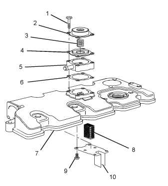
1 Remove bolts (1) and remove the assembly of cover (2), spring (3) and diaphragm (4). Note the
orientation of cover (2).
Remove spring (3) and diaphragm (4) from cover (2).
3 Remove adapter (5) and joint (6) from valve mechanism cover (7).
Note: Make a temporary mark in order to show the orientation of the adapter for installation.
4 If necessary, follow Steps 4.a through 4.c in order to remove the gauze for the breather.
Remove valve mechanism cover (7).
Remove screws (9) and carefully remove plate (10).
Remove gauze (8) from valve mechanism cover (7).
Installation Procedure
2
1 Clean all parts and inspect all parts. Replace any parts that are worn or damaged. Ensure that the cavity for the breather in the valve mechanism cover is clean. Ensure that vent hole in adapter (5) and the vent hole in cover (2) are free from restriction.
2 If necessary, follow Steps 2.a through 2.d in order to install the gauze for the breather.
Install gauze (8) to valve mechanism cover (7).
Position plate (10) on valve mechanism cover (7) and install screws (9).
Tighten screws (9) to a torque of 1.5 N·m (13 lb in).
Install valve mechanism cover (7). Refer to
Disassembly and Assembly, “Valve Mechanism Cover – Remove and Install” for the correct procedure.
3 Position a new joint (6) on the valve mechanism cover and install adapter (5).
Note: Ensure the correct orientation of the adapter.
The vent hole should face upward.
4 Install diaphragm (4) and spring (3) to cover (2).
5 Position the assembly of cover (2), spring (3) and diaphragm (4) onto valve mechanism cover (7).
Note: Ensure the correct orientation of the cover.
6 Install bolts (1). Use Tooling (A) in order to tighten bolts to a torque of 3 N·m (27 lb in).