This instruction show you guide on how to solve JCB JS140 excavator trouble code C1020-13 fuel level sensor open circuit error.
Related Contents:
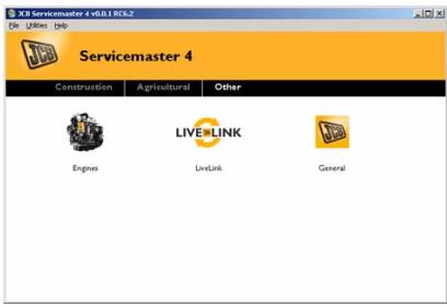
2025 JCB ServiceMaster 4 v25.1.0
2017 JCB Parts Plus+ and Repair Service Manual
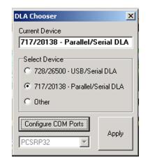
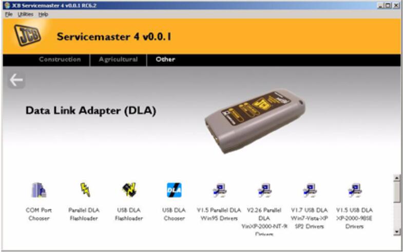
JCB DLA Electronic Service Tool
2025 JCB WinEEM5 WinEEM4 JCB Service Tool 9.0
C1020-13:Fuel Level Sensor Open Circuit (For JS140 Side mounted Sensor).
Possible Cause:
1 Fuel sensor not connected to machine revolver harness.
2 Faulty fuel sensor.
3 Faulty Wire harness.
4 Faulty Display ECU.
Diagnosis:
1 Check fuel senor connection with machine revolver harness.
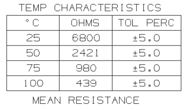
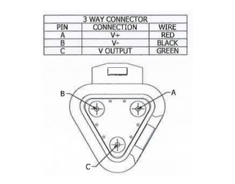
2 Check the resistance output of fuel sensor between machine grounds & Pin no “B” of fuel sensor. Fuel sensor output shall be between 12Ω – 100Ω Refer below photograph for fuel sensor connection.
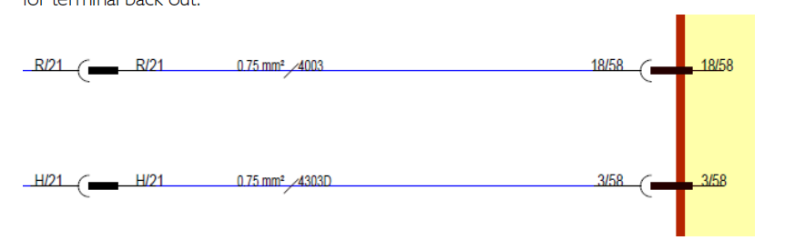
3 Check connectivity of wire no. 8028 from fuel sensor to DECU.Refer machine electrical circuit 336/F3635 for fuel sensor connection.
Corrective Action:
1 Connect properly fuel sensor with revolver wire harness.
2 Replace the fuel sensor.
3 Replace the Faulty wire harness.
4 Replace the faulty display ECU.