Posted on

How to Use JPRO Commercial Vehicle Graph Heavy Duty Data Function

JPRO Commercial Vehicle  Graph window displays various data items and parameters in a constantly updating graph format, allowing you to view trending information. The graph is configured and launched from the Data Monitor.


What You Need?

2023 JPRO Commercial Vehicle Diagnostics

Noregon JPRO DLA+ 2.0 Adapter Kit


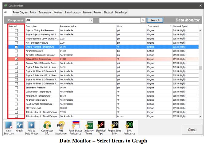
1.Select data rows of interest in the Data Monitor by clicking the Selected checkbox. You may clear any previously selected rows by selecting the Clear Selection button.

2.Click on the Graph button.
3.The Graph window is displayed. The data items you selected will be plotted on the graph over time.

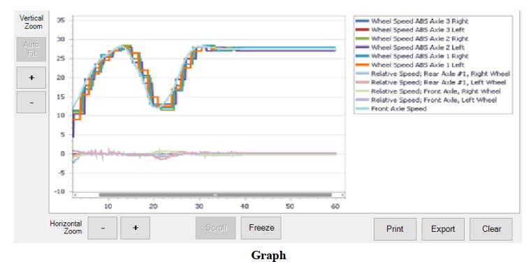
4.To customize the display:
a.Hover the cursor over the graph to see the value plotted.
b.You can zoom each axis of the graph independently by clicking either the + or – button.
c.Clicking the Auto Fit button will resize the graph to show all plotted data items.
d.The Scroll button automatically moves the graph view to the most current information.
e.The Freeze button allows you to keep the graph view from moving, letting you easily study the data while the graph continues to run.
f.Print allows you to print the current graph view. A color printer is strongly recommended.
g.Export displays a save file dialog. Up to the last 5 minutes of currently graphed data can be saved to the desired location as an XML file.
h.The Clear button removes all data from the graph and begins capturing new data.

Posted on

JPRO Diagnostics DLA+ 2.0 Medium Duty Truck Data Bus Connection Guide

This post show you guide on how to build connect between medium duty truck and JPRO DLA+ 2.0 adapter with JPRO diagnostic software.


Tools and Software You need:

Noregon JPRO DLA 2.0+ Adapter

JPRO 2023 Diagnostic Software


Procedures:

Connect a supported Noregon adapter using the appropriate OBD II cable provided.
If using a USB connection, also connect the USB cable to the computer running JPRO Commercial Vehicle Diagnostics.

Ford vehicles require the OBD II cable with the red connector
GM (GMC or Chevrolet) vehicles require the OBD II cable with the yellow connector
Sprinter vehicles require the OBD II cable with the blue connector when using a DLA+ or DLA+ Wireless adapter or the OBD II cable with the gray connector when using the DLA+ 2.0 or DLA+ 2.0 Wireless adapter.

Hino and Isuzu vehicles require OBD II cable with either the blue or gray connector.
1.Select the F8 key or the Connect button on the main toolbar.
2.You will be prompted for the connection type. Select the Medium/ Light Duty OBD connector button. NOTE: If you have a Demo license, this button will not be available.


3.The application will try to connect to the vehicle data bus to read the VIN.
4.The application will display the vehicle information. Verify and correct, if necessary, the VIN,
Make, Model, Year and Engine. If you do not have a 17 digit VIN available, or the vehicle information is incorrect, then select the make, model, year and engine.
If the vehicle is not currently supported, you may attempt to connect as Generic OBD II. However, when connected as Generic OBD II, only emissions related faults and sensor data will be available.

5.A confirmation prompt may be displayed if the vehicle year is not supported or if the vehicle make, model, and engine is not supported in any year.
a.If the vehicle year is not supported, a prompt to choose to connect with proprietary support or as
Generic OBD II will display.

Select Yes to proceed with the connection proprietarily. Select No to proceed with a Generic OBD II connection.
b.If the vehicle make, model and engine is not supported in any year, then a confirmation prompt to connect as Generic OBD II will display.

6.The application will now try to connect to the vehicle data bus using a supported adapter. Progress information will be displayed while the initial download of vehicle and sensor data is completed.

7.The Vehicle Readiness, Fault Code Information and Key Data Points windows are displayed.

Posted on

How to Bendix Virtual Truck Demo Connection Function?

The demo truck feature demonstrates the tests and data available to various Bendix ECU versions and configurations.
Select from the available options to create a custom demo connection to explore.
NOTE: This is for demonstration purposes only. Tests and data may not function realistically.


Related Products:

2023 JPRO Commercial Vehicle Diagnostics Software Download & Installation Service
2023 Bendix Acom Pro V3 ABS ATC Diagnostic Software Installation Service


Procedures:

1.Select the F8 key or the Connect button on the main toolbar.
2.You will be prompted for the connection type. Select the Truck Simulators button.
3.Select the vehicle to simulate.

How to Bendix Virtual Truck Demo Connection Function (1)

4.Choose Bendix Demo Truck from the Select Virtual or Demo Truck screen.

5.Select the desired System option to enable appropriate required and optional ECU selections. Once all required selections have been made the Connect button will become available. Select Connect to begin the demonstration.

How to Bendix Virtual Truck Demo Connection Function (2)

6.The demonstration will behave like a Heavy-Duty vehicle connection. The Vehicle Readiness, Fault Code Information and Key Data Points windows are displayed with demo faults and data from the selected ECUs.Initially, the top portion of the Vehicle Readiness window will indicate the gathering the vehicle’s information.Once all vehicle information has been retrieved, the health of the vehicle is displayed.

How to Bendix Virtual Truck Demo Connection Function (3)

7.Explore JPRO features such as Data Monitor and bi-directional tests to view the options available for the selected ECUs.
NOTE: The ability to initiate a Recording or Submit Warranty are not available when connected to the Bendix Demo Truck.
8.Select the F8 key or the Disconnect button on the main toolbar to close the demo truck session.