This instruction show you guide on how to remove and install engine electronic control unit harness connectors for JCB 200X series excavator.
Related Contents:
2026 JCB ServiceMaster 4
2017 JCB Parts Plus+ and Repair Service Manual
Integrity
The engine electronic control unit (ECU) and the devices connected to it are of rugged construction and inherently more reliable than the interconnecting wires and connectors.
Before testing or renewing electrical devices ensure that the relevant wires and connectors are fitted and functioning correctly. In many instances electrical faults are easily remedied by rectifying faulty wires, connectors or earth points. Before proceeding isolate the electrical system by disconnecting the battery. See the applicable machine documentation for the correct procedure.
1 Wiring Harness – Visually inspect the interconnecting wires and connectors for signs of damage. Check the following
Chaffed wires – Intermittent short circuits
Cut wires – Open circuits. Possibly caused by wires becoming trapped in machine mechanical mechanisms.
Broken wires – Open circuits. Possibly caused by incorrect routing or tying of wires allowing insufficient length for machine movements.
Melted wires – Intermittent short circuits. Possibly caused by contact with turbocharger or exhaust systems.
2 Connectors – Visually inspect the applicable connectors. Check the following
Coupling – Intermittent open circuits. Ensures that connectors are coupled correctly with the locking mechanisms properly latched. Informally known as “Backed out” terminals that are not seated correctly inside connector housings, terminals could be sat low within the housing causing Intermittent Connections or Open circuit faults.
Damage – Intermittent open or short circuits. Inspect the connectors for signs of physical damage such as broken housings or locking clips. Connectors can also melt if they come into contact with hot exhausts or turbochargers. Uncouple the connectors and inspect the pins for damage such as corroded, bent or broken pins. DO NOT TOUCH the connector pins on the engine electronic control unit (ECU). Broken connectors must be renewed.
Contamination – intermittent open or short circuits. Uncouple the connectors and inspect the inside for signs of contamination, typically with water, oil, Diesel Exhaust Fluid (DEF) or hydraulic fluid. If necessary clean the connector pins and receptacle using a cotton bud or similar. DO NOT TOUCH the connector pins on the engine electronic control unit (ECU). If water contamination is evident allow it to dry completely before coupling the connectors. Carefully inspect any sealing elements for signs of contamination or damage. Fluids can “creep,” along wires so always check surrounding wires and connections for contamination if a instance of contamination is found.
3 Earth Points – locate the electrical earth points on the engine and machine. make sure that the wires terminals are correctly fitted. Make sure that the earth point is free from contamination and corrosion.
Engine Electronic Control Unit – Harness Connectors Remove and Install
Removal
The following procedure is for one connector. The procedures for both connectors are identical. Be sure to fit the connectors to their original positions.
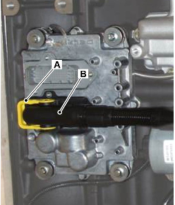
1 Rotate the locking lever A in the direction of the arrow.
2 Grasp the connector B and pull it carefully from its receptacle on the ECU. DO NOT tocuh the connector pins on the ECU.
1
Installation
Installation is the reversal of removal but note the following
1 Make sure that the locking lever A is fully latched in the lock position.