Posted on

How to Perform Case IH 20 Series Axial-Flow Combine Low Pressure Standby

CASE IH 20

This instruction show guide on how to perform CASE IH 20 series Axial-Flow combine low pressure standby.This test is used to determine low-pressure standby.There are two items responsible for low pressure standby,the 375-400 PSI (26-28 bar)spring on the flow compensator spool and the 0.078 mm (0 .031 in)orifice in the steering hand pump –which creates back pressure in the signal line of approximately 50-150 psi.The 375-400 PSI (26-28 bar)spring plus the back pressure will equal low-pressure standby.The following test will show the spring setting of the flow compensator spool.

CASE IH 20

Related Contents:

CNH DPA5 Diagnostic Kit

2026 CNH EST 9.14 Diagnostic Software

2026 CASE eTimGo Repair Manuals


TEST PROCEDURE

1 Attach a 69 bar (1000 psi)gauge to the signal line pressure test port (14)on the main valve assembly.It is recommended to install a needle valve in the test hose to prevent damage to the gauge.With the needle valve closed,start the engine.At low idle,open the needle valve on the gauge.Make sure that the steering wheel is not moved or that other hydraulic functions are not activated otherwise the gauge could be damaged. The signal line pressure should be approximately 50-150 PSI (3 .45-10.4 bar).Record this number for use later.


2 Then attach the SAME 69 bar (1000 psi)gauge to the PFC pump pressure test port (13) on the main valve assembly.With the needle valve closed,start the engine.At low idle open the needle valve on the gauge.Make sure that the steering wheel is not moved or that other hydraulic functions are not activated otherwise the gauge could be damaged.The PFC pump pressure port should read 375-400 PSI (26-28 bar)above the reading that was recorded from the signal line.

If the PFC pump pressure port does not read 375-400 PSI (26-28 bar)ABOVE the signal line, adjustment of the flow compensator spool spring is required.The adjustment procedure is as follows:


Example Signal line pressure port reading 112 psi (7 .7 bar) Flow compensator spool spring setting +400±25 psi (27 .5 bar

PFC pump pressure port reading AFTER adjustment 512±25 psi (35 .3 bar)


3 Remove the cap for the adjustment screw located on the compensator.

4 Loosen the jam nut.

5 Use an allen wrench to adjust the pressure to match the number calculated.(See example.)

6 Tighten the jam nut.Repeat test to verify the low-pressure standby setting.

7 If not correct,make adjustment again.If it is correct,replace the cap.
Posted on

How to Bleeding the Park Brake for CASE IH 20 Series Combine

How to Bleeding the Park Brake for CASE IH 20 Series Combine

How to bleed the park brake for CASE IH 20 series Axial-Flow combine.

How to Bleeding the Park Brake for CASE IH 20 Series Combine


Related Contents:

CNH DPA5 Diagnostic Kit

2025 CNH EST 9.13 Diagnostic Software

CNH eTimGo Repair Manuals


Any time the parking brake is disassembled or lines removed, the system will require bleeding.

To bleed the system proceed as follows:


REMEMBER: As the brake switch must be depressed several times while bleeding, this job has to be done with two persons.


1 Park the combine on level ground and block the wheels adequately to prevent the combine form rolling.

2 Raise the header and engage the header safety latch. Stop the engine.

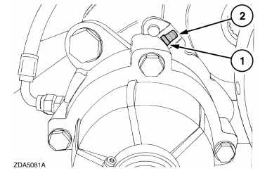
3 Remove the rubber cap (2) from the bleed screw (1).

4 Slide a transparent hose over the bleed screw to catch the oil when bleeding.

5 Start the combine engine.

6 Disengage and engage the parking brake a few times.

7 At the same time open the bleed screw until air free oil escapes through the bleed screw.

8 Engage the parking brake and stop the engine.

9 Remove the transparent hose and reinstall the rubber cap, (2).

10 Check the proper hydraulic reservoir for proper oil level.

Posted on

CASE IH 20 Series Combine Bleeding Service Break Operation

CASE IH 20 Series Combine Bleeding Service Break Operation (1)

CASE IH agriculture 7120-9120 series axial-flow combine bleeding service break operation guide.


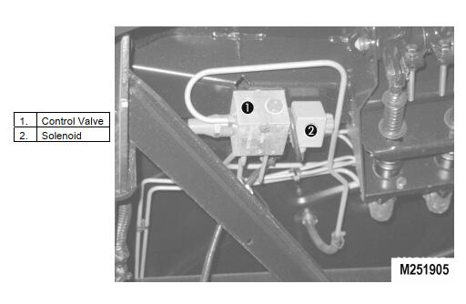
The European machines may be equipped with a pressure limiting valve to prevent the main drive wheels from locking up. The valve incorporates a solenoid L-32 that when activated will expose the brake pressure lines to a relief.

CASE IH 20 Series Combine Bleeding Service Break Operation (1)


Related Contents:

CNH DPA5 Diagnostic Kit

CNH EST 9.10 Diagnostic Software

CNH eTimGo Repair Manuals


Any time the brake is disassembled or lines removed, the system will require bleeding. To bleed the system proceed as follows:

REMEMBER: As the brake pedal must be depressed several times while bleeding,this job has to be done with two persons.
CASE IH 20 Series Combine Bleeding Service Break Operation (2)

Procedures:

1 Park the combine on level ground and block the wheels adequately to prevent the combine form rolling. The engine does NOT need to be running.
2 Raise the header and engage the header safety latch. Stop the engine.
3 Verify that the brake reservoir is filled.
4 Slide a transparent hose over the RH outside bleed screw to catch the oil when bleeding.
5 Cab Operator holds down the LH brake pedal and pumps RH brake pedal.
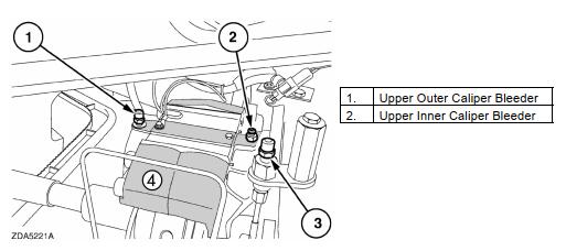
6 Bleed Operator loosens RH outside caliper bleed valve (#1 in photo) to allow the air to bleed out, and then retightens it when oil comes out of the port.
7 Operator then loosens RH inside caliper bleed valve (#2 in photo) to allow the air to bleed out, and then retightens it when oil comes out of the port.
8 Operator in cab then holds down RH brake pedal and pumps LH brake pedal.
9 Repeat steps 5-7 for the LH side.
10 Check for the reservoir for proper oil level