Perkins Phaser/1000 Series Engine Measurement of Inlet Valve
Related Contents:
Perkins SPI2 2018A Service and Parts Catalogs
Currently, the maximum clearance between the valve stem and the guide is 0,13 mm (0.005 in) for inlet valves and 0,15 mm (0.006 in) for exhaust valves. As these clearances are difficult to check in service, it is recommended that the procedure given below is used.
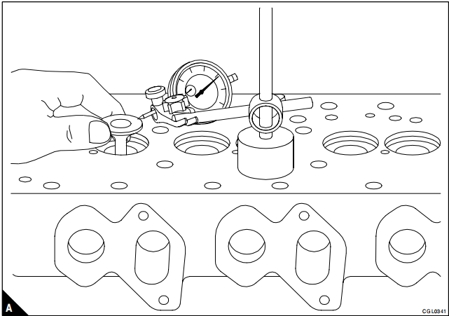
Put a new valve in the valve guide. With a dial test indicator on the face of the cylinder head, lift the valve 15,0 mm (0.6 in).
Move the valve radially across the axis of the cylinder head away from the gauge. With the valve held in this position, zero the gauge against the valve head (A). Move the valve radially across the axis of the cylinder head towards the gauge. Make a note of the reading on the gauge. If the reading is equal to or greater than the data given below, a new valve guide must be fitted.
Maximum permissible clearance with a valve lift of 15,0 mm (0.6 in):
Inlet guide: 0,24 mm (0.009 in)
Exhaust guide: 0,32 mm (0.013)

