This instruction show you guide on how to inspect rod and cap for John Deere 9.0L OEM engine.
Related Contents:
John Deere Service Advisor EDL2
2024 John Deere Service Advisor 5.3.235
John Deere Parts ADVISOR EPC 2025
Inspect Rod and Cap
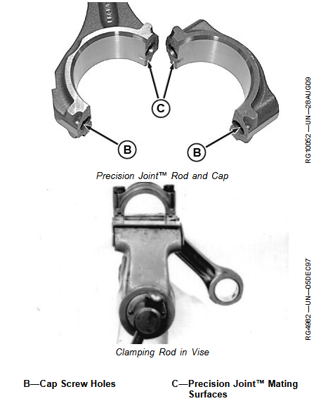
1 Inspect rod and cap for wear or damage, such as chips or nicks in the joint areas.
IMPORTANT: Do not nick the joint surfaces of rod and cap. This is very critical on Precision Joint™
rods to assure proper seating. Never scrape joint surfaces (C) with a wire brush or other tool; the
interlocking mating surfaces must be preserved.
2 Inspect in and around cap screw holes (B) in cap. If any defects are found, replace rod and cap.
3 Carefully clamp rod in a soft-jawed vise (cap end upward).
4 Install cap WITHOUT bearing.
IMPORTANT: Never use new connecting rod cap screws when checking rod bore I.D. Use new cap screws only for final assembly of connecting rods.
5 On Precision Joint™ connecting rods: Initially tighten rod cap screw closest to piston end, then tighten other cap screw to the following specifications.
Specification
Precision Joint™
Connecting Rod Cap
Screw—Torque……………… 95 N·m (71 lb-ft) plus 90–100° turn clockwise
See TORQUE-TURN CONNECTING ROD CAP SCREWS, described later in this group.
1
6 Using an inside micrometer, measure rod bore atcenter of bore and record measurements as follows:
- At right angle to rod/cap joint (A).
- At 45° left of measurement step “A” (B).
- At 45° right of measurement step “A” (C).
Specification
Connecting Rod Bore
(Without Bearings)—ID…………..87.487—87.513 mm (3.444—3.445 in.)
7 Compare the measurements. If difference between the greatest and least measurement is more than 0.04 mm (0.0016 in.), the rod and cap are out-of-round.
Replace both connecting rod and cap.
Specification
Connecting Rod
Bore—Maximum
Out-of-Round…………………………………………………0.025 mm (0.0010 in.)
8 Measure rod’s piston pin bore-to-crankshaft bore center-to-center dimension (A) and compare with specification given. If measurement is not within specification, replace rod.
Specification
Centerline of Piston
Pin Bore-to-Crankshaft
Bore—Dimension…………………..217.95—218.05 mm (8.581—8.585 in.)

